Bitzer applications engineering is available for review of the final compressor selection and to provide recommendations as necessary. 40 low starting current balanced magnetic field.
Goldair Specialized In Electronic Instruments
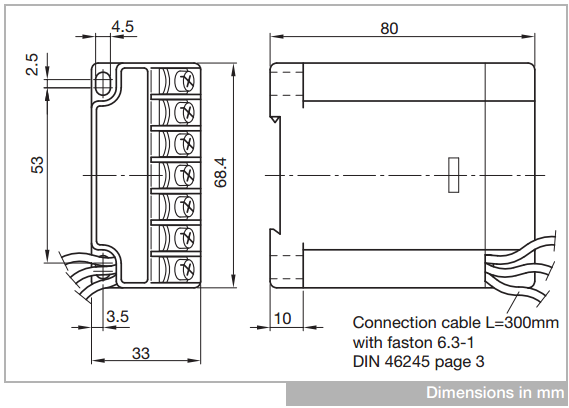
Bitzer screw compressor wiring diagram. Bitzer will not be responsible for system engineering or re engineering. Pco5 medium with built in eev driver for bitzer csh screw compressors software installed kit pco5bz010k in addition the following are available to complete the system. Especially if quality issues are suspected such as soldering reliability unsuitable connections wrong polarities and further problems which might be revealed in a photo. Pgd1 user terminal for panel installation 8 rows by 20 columns pgd1000f00 4. Ers of the reciprocating compressor. The engine and discharge gas temperature oil supply and application limits.
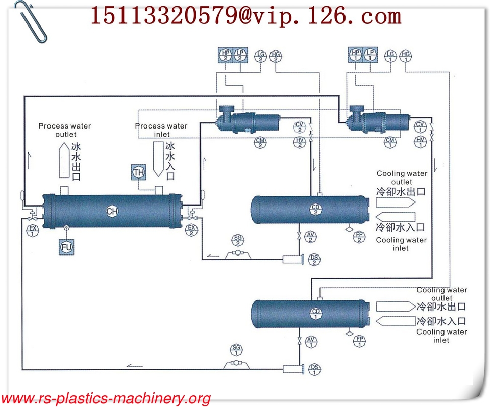
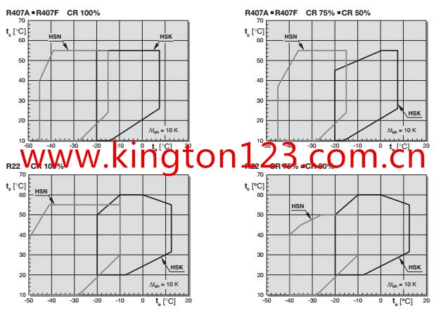
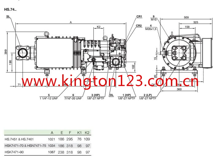
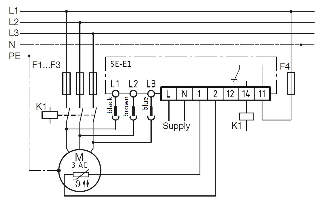
The terminals m1 m2 or t1 t2 on the com pressor and 1 2 on the protection device must not come into contact with the control voltage or. Special features of the bitzer motors many years of experience with part. For replacement compressor selection a capacity comparison of each compressor is given in table 1 and dimension information is given in table 2. It protects the compressor from operating under critical conditions. Schematic wiring diagrams see chapter schematic wir ing diagrams page 9. 8 cylinder compressors 60.
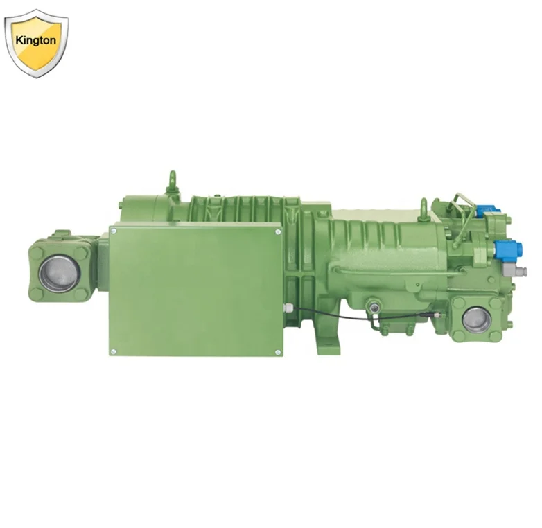
Horizontal screw compressor to a fusheng bsr compressor. Driver for bitzer csh screw compressors software flstmbsde 2. Size information is given in table 2. The suction and discharge connection sizes are different between the bitzer cs and fusheng bsr compressors. This includes final compressor selection condenser sizing refrigeration line sizing oil system electrical wiring or components. Cs screw compressor troubleshooting guidelines 01 april bitzer compressor wiring diagram sometimes a photo can support engineers troubleshoot your design.
The module switches the oil heating on and off and depending on the equipment of the compressor the start unloading the compressor cool. Notice potential failure of the compressor protection device and the motor due to improper connec tion andor faulty operation. 31 schematic wiring diagram and motor connection 3 raccordement électrique 31 schéma de fonctionnement et.
Gallery of Bitzer Screw Compressor Wiring Diagram