Install module wiring in accordance with the job draw ings and appropriate wiring diagrams. Fmm 1a fmm 101a fzm 1a fdm 1a.
Notifier Fcm 1 Rel Accessories Notifier
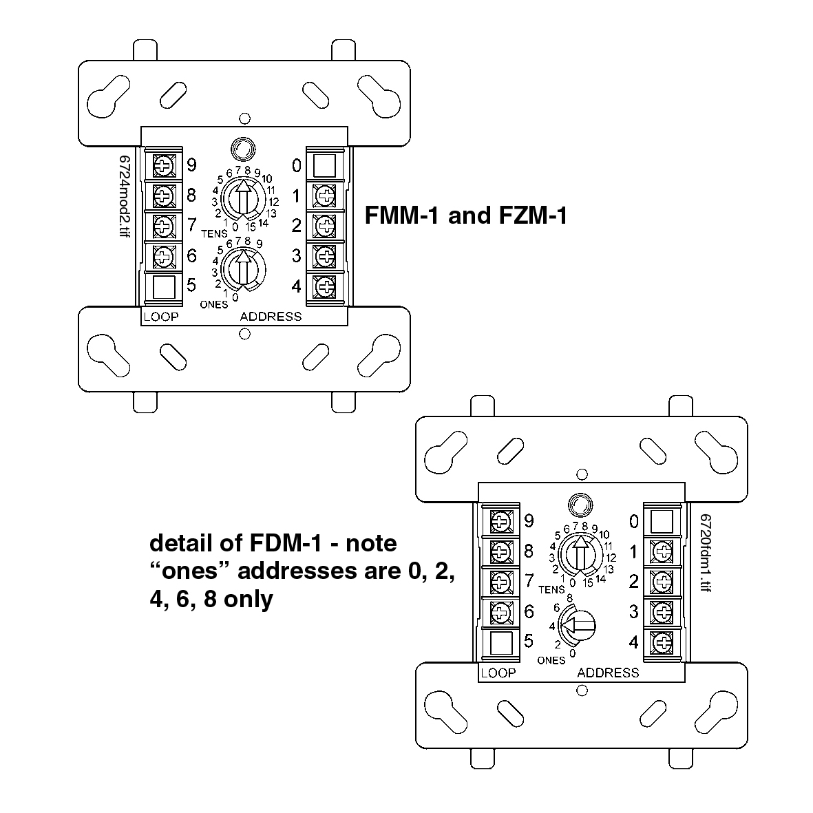
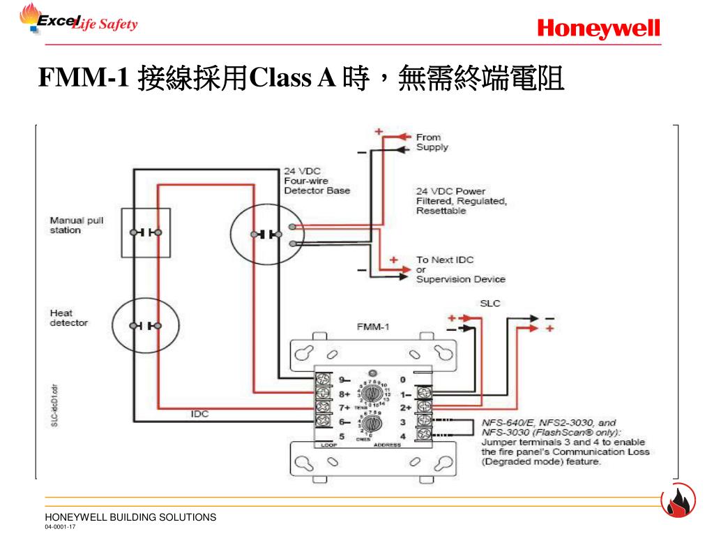
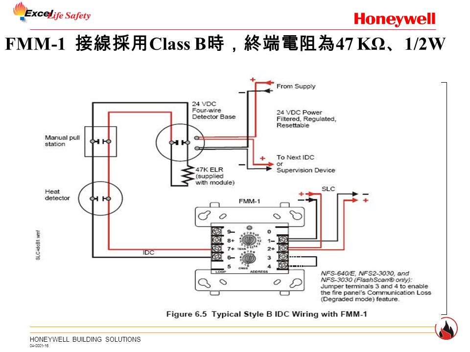
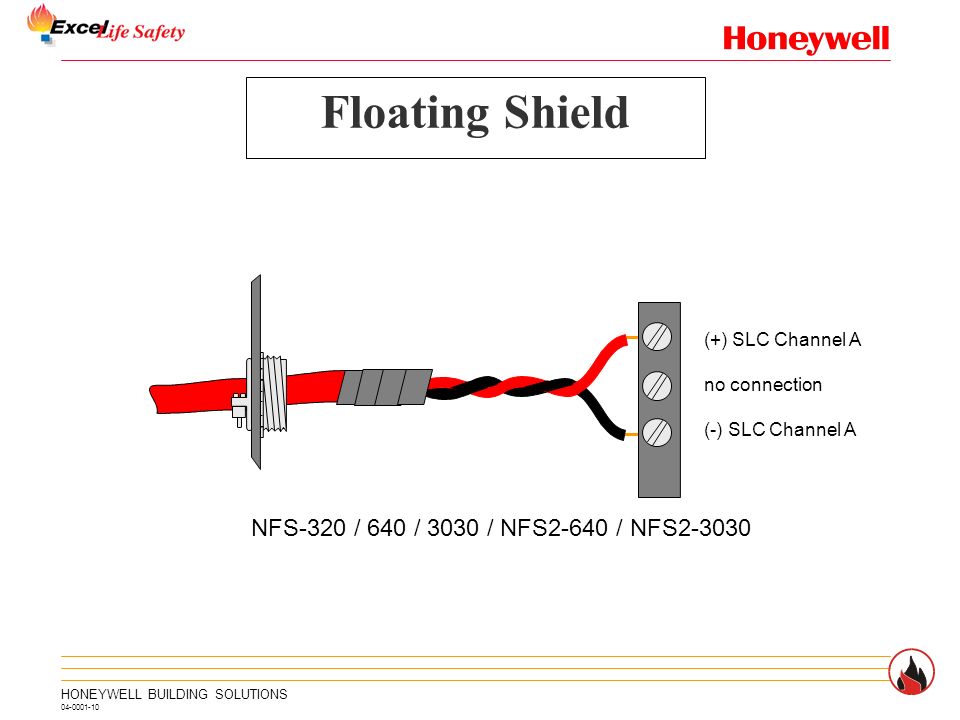
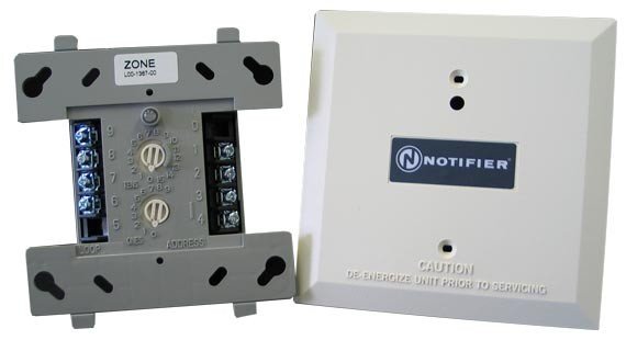
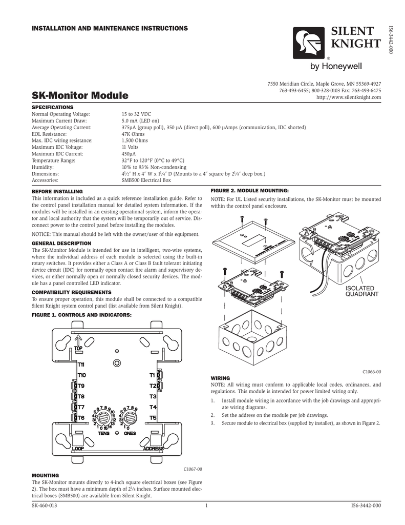
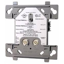
Fmm 1 wiring diagram. Module mounting with barrier. Any number of ul listed contact closure devices may be used. Monitor modules model numbers include the fmm 1 fmm 101 fzm 1 and fdm 1. All wiring shown is supervised and power limited. All wiring must conform to applicable local codes ordinances and. Some panels support extended addressing.
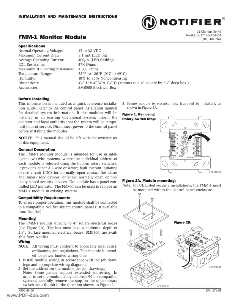
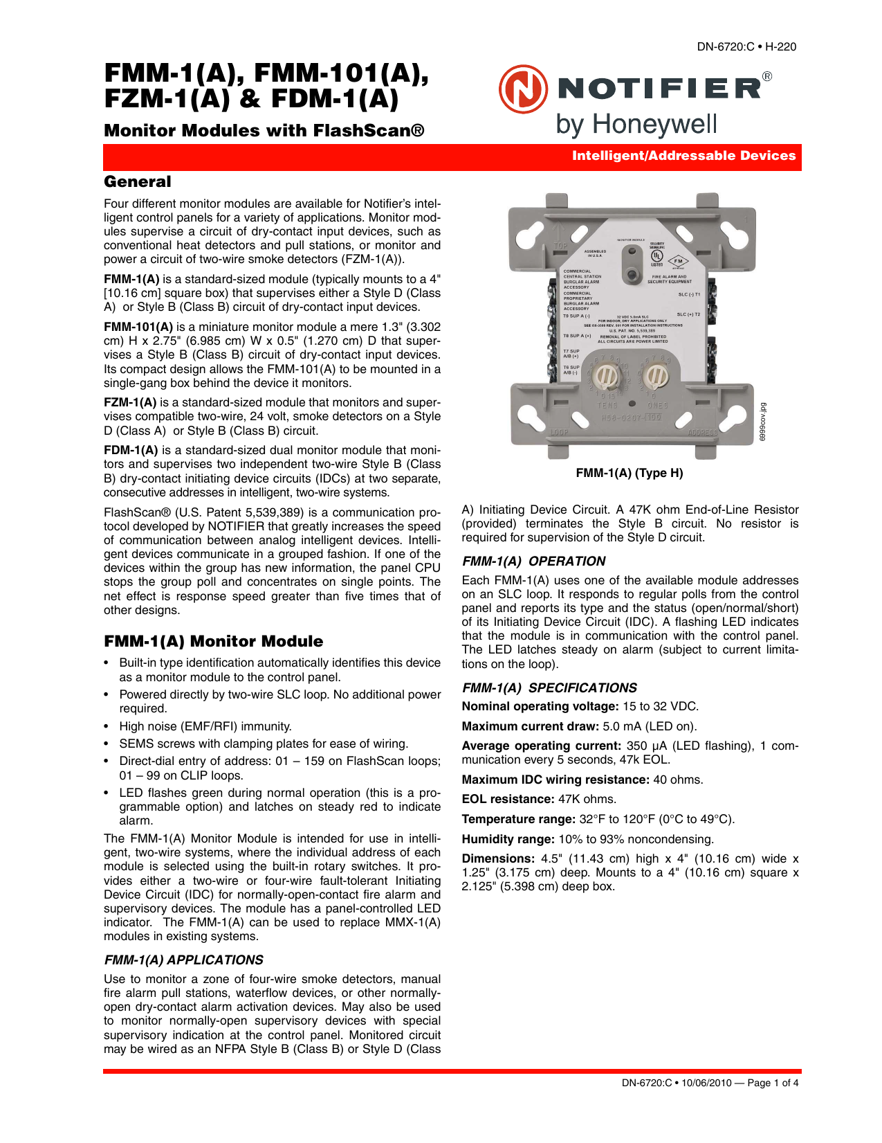
Fmm 1 connect modules to listed compatible notifier control panels only. 15 to 32 vdc. Modules are intended for power limited wiring only. This module is intended for power limited wiring only. Set the address on the module per job drawings. Maximum slc current draw.
Direct dial entry of address. Some panels support extended addressing. The fmm 101a module is intended to be wired and mounted without rigid connections inside a standard electrical box. Typical fault tolerant notification appliance circuit con figuration nfpa style z. Install module wiring in accordance with the job drawings and appropriate wiring diagrams. A78 2611 11 a78 2610 08 specifications normal operating voltage.
This module is intend ed for power limited wiring only. Maximum slc current draw. Sems screws with clamping plates for ease of wiring. 15 to 32 vdc. All wiring must conform to applicable local codes ordinances and regulations. 15 to 32 vdc maximum current draw.
Set the address on the module per job drawings. All wiring must conform to applicable local codes or dinances and regulations. Typical notification appliance circuit configuration nfpa style y. 65 ma led on temperature range. Removing rotary switch stop. Page 5 wiring diagrams this page.
4675 h x 4275 w x 14 d mounts to a 4 square by 218 deep box specifications for frm 1. 32f to 120f 0c to 49c dimensions. Dn 6724 040504 page 3 of 4 the face plate 6724facewmf wiring diagrams the following wiring diagrams are provided. Install contact closure devices per manufacturers installation instructions. Built in type identification automatically identifies this device as a monitor module to the control panel. Led indication for normal or off normal indication.
65 ma led on. Install module wiring in accordance with the job drawings and appropriate wiring diagrams.
Gallery of Fmm 1 Wiring Diagram