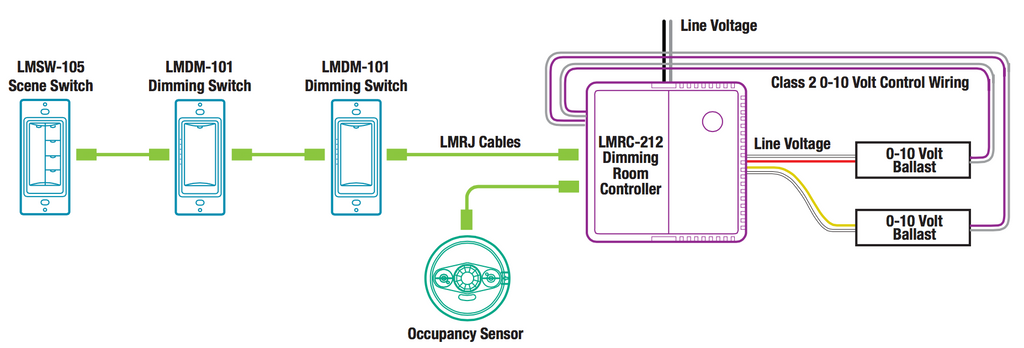
The lmrc 101 has one load controlling relay and the lmrc 102 has two load controlling relays load a and load b. Lmrc 212 and the lmrc 212 347 room controllers each have two load relays.

46a699 Watt Stopper Dimming Wiring Diagram Wiring Library
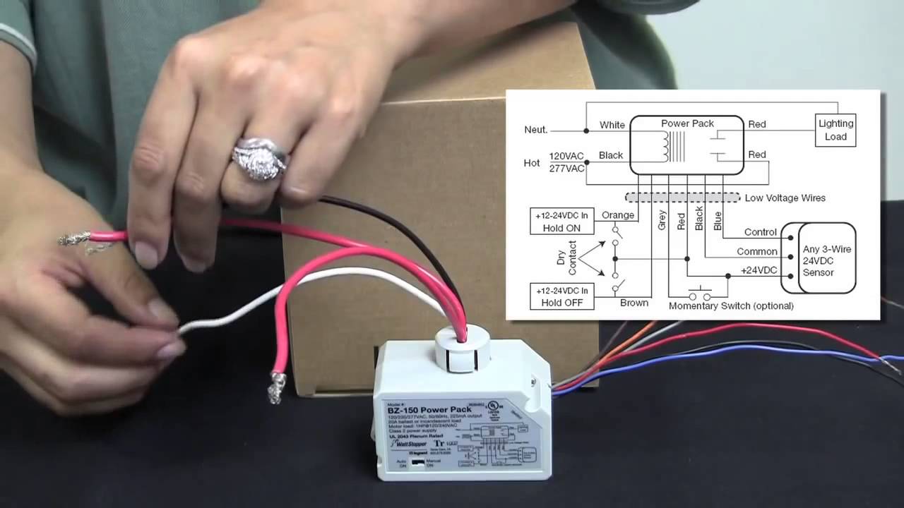
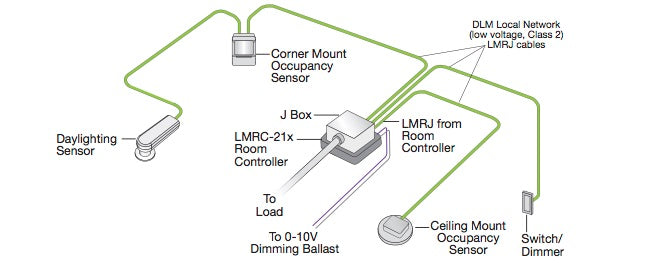
Lmrc 101 wiring diagram. The lmrc 211 is rated for up to 20a. 90 151 lmrc 101 and lmrc 102 three relay wiring diagram pdf 6568kb 90 952 large office wdaylighting png 262kb 90 952 large office wdaylighting. Lmrc 100 series room controllers are ideal for single or multiple zone onoff lighting control applications. Lmrc 221 75 c copper wire only santa clara ca 8008798585 industrial control equipment 46a9 indoor use only mounting the controller the room controller mounts to a four square deep junction box using the included mounting plate with the hinge pins extending away from the box as shown. Up to four room controllers can be interconnected on the dlm local network. The next highest serial number would have load 3 and load 4 and so forth.
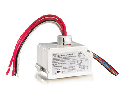
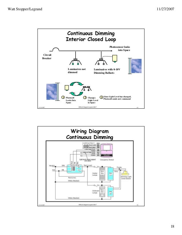
Do not reclassify and install as class 1 or power and lighting wiring. Wattstopper lmrc 101 controller pdf manual download. In a dlm local network with only lmrc 212 or lmrc 212 347 room controllers the room controller with the highest serial number is the master carrying load 1 and load 2. The dimming curve must be set for proper operation. Mounting inside a j box. For class 2 dlm devices and device wiring.
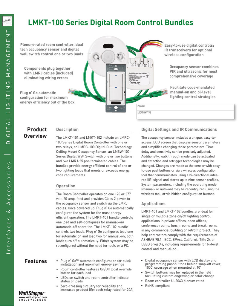
Lmpl 101 plug load room controllers include a 12 127mm threaded nipple and locking ring. The lmrc 101 helps specifiers comply with basic ashrae 901 requirements while the lmrc 102 is designed for bi level switching in iecc epact california title 24 or leed projects. The next highest serial number would have load 3 and load 4 and so forth. All line voltage wiring is 12 awg. Lmrc 101 and lmrc 102 room controllers lmrc 101102 connectivity the lmrc 101 and lmrc 102 are powered by 120230277vac 5060hz. The lmrc 222 has two load outputs.
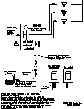
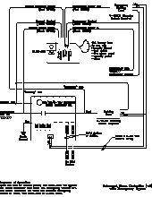
Both controllers are appropriate. Sample connection diagram with class 1 class 2 dimming control wiring 44 112mm 32 83mm 2 50mm load onoffdim buttons red configuration led blue load status leds class 2 dlm local network ports not shown. Lmpl 101 lmpl 101 u 120vac 5060hz. The lmrc 211 347 is rated for up to 15a. Mounting and wiring room controllers controls mounting j box load line mounting outside a j box plenum space. Class 1 0 10v and power wires configuration button class 2 0 10v wiring terminal ports cable tie ring lmrc 112 line voltage.
Terminate wiring according to wiring diagram. Two lmpl andor lmrc room controllers maybemountedtothej box. In a dlm local network with only lmrc 222 room controllers the lmrc 222 with the highest serial number is the master carrying load 1 and load 2. 48 communicating devices including up to 4 lmrc 10x series andor lmpl 101 controllers and lmpb 100. To be connected to a class 2 power. Installation shall be in accordance with all applicable free topology up to 1000 max.
Gallery of Lmrc 101 Wiring Diagram