Niftylift hr12 wiring diagram s13 240 fuse box wiring library niftylift hr12 wiring diagram wiring diagram is a simplified tolerable pictorial representation of an electrical circuit. All you need is the serial number of your machine and its all done in three easy steps.

Lc 2891 Ballast Wiring Diagram On T5 Fulham Ballast Wiring
Niftylift hr12 wiring diagram. Hr12 lifting systems pdf manual download. Niftylift serial numbers have prefixes for example 04 17 21 etc. Also when lowering the. If you need access to the technical documentation for your niftylift then you need the manuals and drawings search page on the niftylift uk website. It shows the components of the circuit as simplified shapes and the facility and signal links surrounded by the devices. There is no need to enter the prefix number just enter the numbers that come after the prefix.
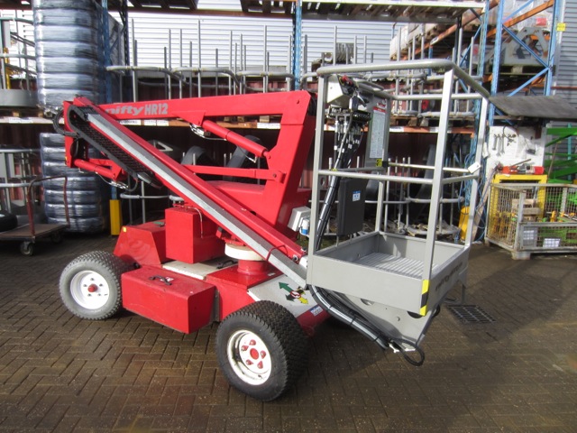
Here is a quick and simple way to access and download all the documentation for your niftylift with our simple online search function. Of any niftylift height rider hr10 or hr12 sp26 or sp34 powered by electric dc diesel d petrolgasoline p engine or a combination of these. Here you can search for manuals and technical drawings schematics for your niftylift. For further technical information circuit diagrams and specific instructions for all maintenance which may need to be carried out by specialist trained personnel see the associated workshop. Put your niftylift machine serial number into the box. Niftylift spseries operating and safety instructions 3 section 14 july 1995 general specification feature hr 10 hr10 n hr 12 hr 12 n maximum height working 32 ft 39 ft 6 in 98 m 12 m maximum height platform 26 ft 33 ft 6 in 8 m 102 m maximum height stowed 6 ft 3 in 6 ft 3 in 19 m 19 m.
To search for a machine enter the serial number in the box and click search. If any doubts exist concerning any points covered in your manual contact your local dealer or niftylift ltd. Whether it be a parts manual an operating safety manual or even an electrical or hydraulic schematic all can be accessed via the manuals and drawings search page and the best part is that its free. Go to the manuals and drawings page. Page 5 important to prevent damage to the cage step it is necessary to elevate the booms a minimum of 250mm 10 in from their stowed position before slewing.
Gallery of Niftylift Hr12 Wiring Diagram