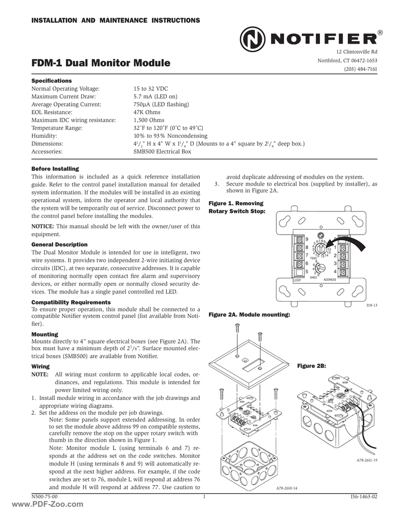
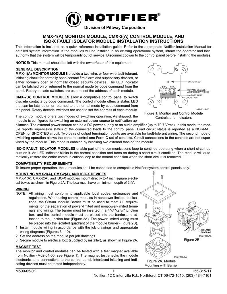
Mounting the fcm 1 mounts directly to 4 square electrical boxes see figure 2a. The mmx 102e mounts in a standard single gang electrical knock.

Siemens Db 11 Smoke Detector Base 8853 500 094151 Fire Alarm
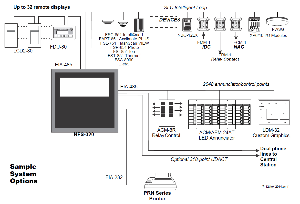
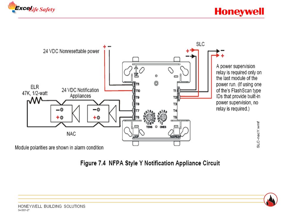
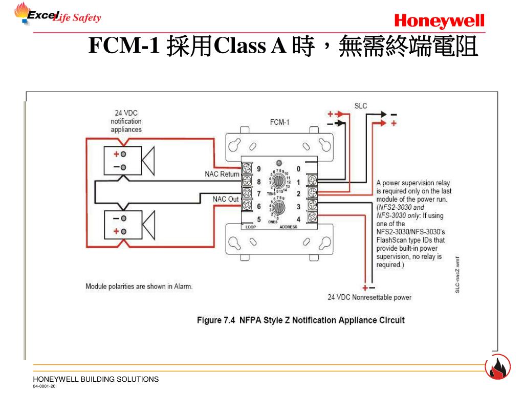
Notifier mmx 1 wiring diagram. The monitored circuit may be wired as an nfpa style b class b or style d class a ini tiating device circuit. Install module wiring in accordance with the job draw ings and appropriate wiring diagrams. The smb500 may then be installed in a 19 rack assembly using notifier 19 rack mounting adapters. The box must have a minimum depth of 21 8. Notifier fcm 1 wiring diagram. The fmm 1a can be used to replace mmx 1a modules in existing systems.
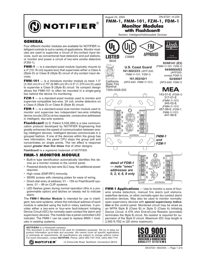
When using control modules in nonpower limited applica. Fmm 1a applications use to monitor a zone of four wire smoke detectors manual fire alarm pull stations waterflow devices or other normally open dry contact alarm activation devices. Monitor modules supervise a circuit of dry contact input devices such as conventional heat detectors and pull stations or monitor and power a circuit of two wire smoke detectors. Mounting the frm 1 mounts directly to 4 square electrical boxes see fig ure 2a. Set the address on the module per job drawings. Surface mounted electrical boxes smb500 are available.
All wiring shown is supervised and power limited. Connecting a releasing device to the fcm 1 rel. All wiring must conform to applicable local codes ordi. Notifier nfs manual online. Install contact closure devices per manufacturers installation instructions. Any number of ul listed contact closure devices may be used.
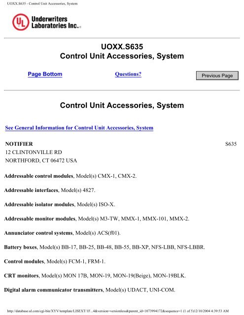
Releasing applications c limited energy cable cannot be used to wire a. Page 5 wiring diagrams this page. Notifier nfse manual online. May also be used to monitor normally open supervisory devices with special. Monitor modules model numbers include the fmm 1 fmm 101 fzm 1 and fdm 1. Surface mounted electrical boxes smb500 are available from notifier.
Compatible notifier system control panel list available from noti fier. Fmm 1 connect modules to listed compatible notifier control panels only. The box must have a minimum depth of 218. Mmx 1e sem screws with clamping plates for ease of wiring mmx 1e lpcb and vds approved installation the mmx 1e mounts in the notifier multi mount enclosure or an smb500. The box must have a minimum depth of 218. Compatible notifier system control panels only list available from notifier.
All wiring must conform to applicable local codes ordi. Fzm 1 has a panel controlled led indicator and can be used to replace mmx 2 modules in existing systems. Connecting a releasing device to a fcm 1 module connecting an. 16112018 16112018 3 comments on notifier fcm 1 wiring diagram. All wiring must conform to applicable local codes ordinances and regulations. Fzm 1 applications use the fzm 1 to monitor a zone of two wire smoke detectors.
Notifiers offers a variety of intelligent monitor modules for diverse applications. This module is intend ed for power limited wiring only. All wiring must conform to applicable local codes ordinances and regulations. Mounting mmx 1a cmx 2a and iso x devices mmx 1a cmx 2a and iso x modules mount directly to 4 inch square electri cal boxes as shown in figure 2a. A 39 k ohm end of line resistor pro.
Gallery of Notifier Mmx 1 Wiring Diagram