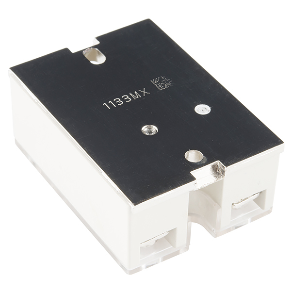
Apc pam sd wht blu yel red org encapsulated relay package typical of 2088 9021 pam 1 and 4098 9843 pam sd specifications continued encapsulated relays see page 2 for dimensions connections 18 awg 082 mm2 color coded wire leads relay 2088 9021 contact ratings 10 a at 120 vac resistive coil. The relay may be energized by one of three input voltages.

Fire Alarm Pam Relay Wiring Diagram Circuit Maclareners
Pam sd relay wiring diagram. A red led is provided on both models. 24 vac 24 vdc or 115 vac. The pam 4 relay provides 100 amp form c contacts and may be energized by a wide voltage range from 9 vdc to 40 vdc. The pam sd may be mounted by using the double sided adhesive tape the self drilling screw or loosely placed in an electrical backbox. Simplex 4098 9843 pam sd relay. Pam 1 the pam 1 relay provides 100 a form c contacts.
A red led is provided which when illuminated indicates the relay coil is energized. Pam 1 the pam 1 relay is an encapsulated multi voltage device providing 10 amp form c contacts. Dozens of the most popular 12v relay wiring diagrams created for our site and members all in one place. 24vdc 24vac or 120vac. A red led is provided which when illuminated indicates the relay coil is energized. 24 vac 24 vdc or 115 vac.
When illuminated it indicates the relay coil is energized. 20 amp contactor wiring diagram format. The pam 4 relay provides 100 amp form c contacts and may be energized by a wide voltage range from 9 vdc to 40 vdc. The pam 1 relay is encapsulated multi voltage device providing 10 amp form c contacts. A red led is provided on both models. The relay may be energized by one of three input voltages.
A red led is provided which when illuminated indicates the relay coil is energized. The pam 1 may be mounted by using the double sided adhesive tape the. Life safety consultants is here to ensure your fire and smoke detectors are always in working order. Wiring diagrams pam 1 pam 2 pam 4. Pam 1 relays contain a red led which indicates when the relay coil is energized. When illuminated it indicates the relay coil is energized.
Wiring diagrams pam 1 pam 2 pam 4. Compatible with the simplex 4098 9756 for fan shut down. 24v ac 24v dc or 115v ac. The input voltages are polarity sensitive and diode protected. Thats why we offer a wide range of replacement parts and components like the simplex pam sd epoxy encapsulated remote relay 4098 9843. The relay may be energized by one of three input voltages.
This relay may not be suitable for continuous duty use at. The pam 1 may be mounted by using the double sided adhesive. 1496 votes last checked. If you need a relay diagram that is not included in the 76 relay wiring diagrams shown below please search our forums or post a request for a new relay diagram in our relay forum. The relay may be energized by one of three input voltages. Pdf epub docx status.
The pam 1 may be mounted by using the double sided adhesive.
Gallery of Pam Sd Relay Wiring Diagram


.png)