Building technologies division pn 315 033290 11. The simplest approach to read a home wiring diagram is to begin at the source or the major power supply.

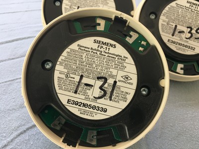
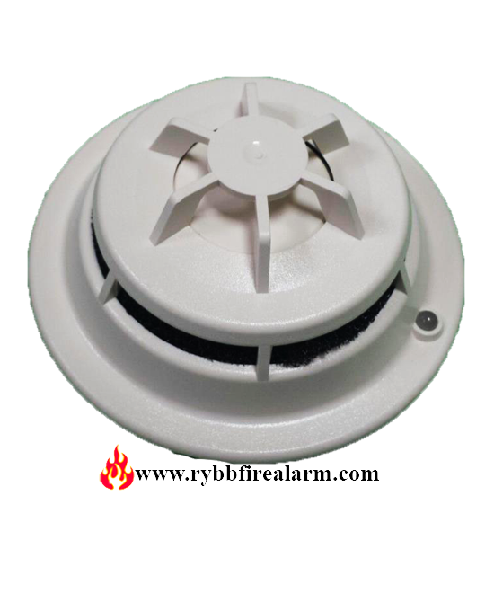
Siemens Hfpt 11 500 033380 Fire Alarm Intelligent Thermal
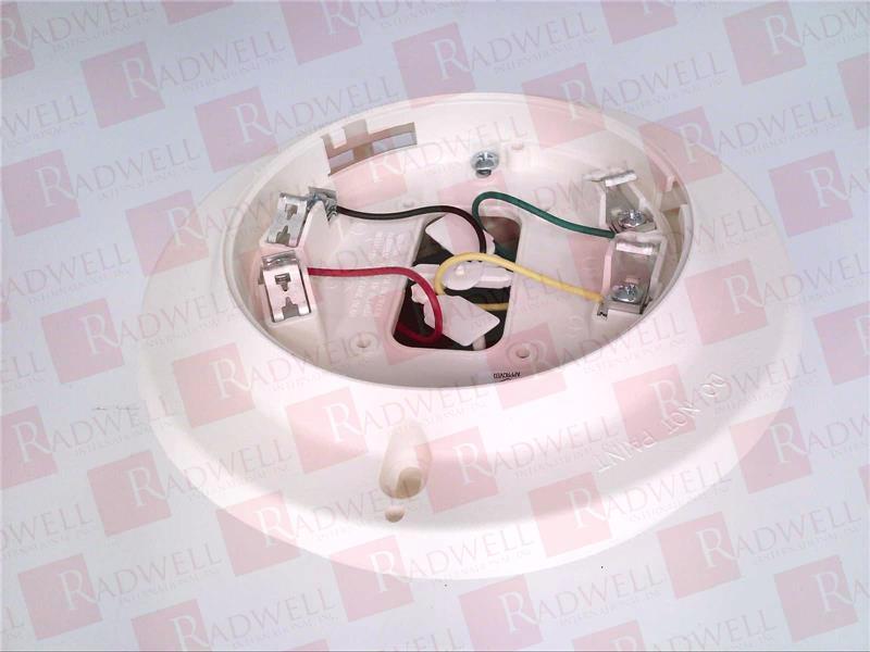
Siemens hfp 11 wiring diagram. Line 1 and line 2 can be either line of the loop. Wiring detector bases for model hfp 11hfpt 11 should be con nected as shown in figure 2. Areas as referenced in nfpa 72. 32 of 0 c 100of 38 c per ul 268268a altitude range. Hfp 11hfpt 11 is a polarity insensitive detector. Model hfp 11 is polarity insensitive which can greatly reduce installation and debugging time.
5 no c 6 nc 5 no c 6 nc do not use an end of line device figure 2 installation and wiring diagram press the more info button again to display a list of firefinder xls devices. Technical data air duct conditions temperature range. Page 2 take up all slack in the outlet box. Ad2 p pe 11 fp 11 hfp 11 hfpo 11 no ad2 pr pe 11 yes ad2 xhr fp 1 hfp o 1 yes for compatible control equipment see charts on the page 14 of this manual. 4 class b wiring. Figure 2 wiring diagram for db 11 11e using fp 11 fpt 11 fs dp fs dpt and fs dt detectors db 11 11e no remote device db hr remote relay base to next base.
Siemens duct detector wiring diagram. Properly dress and position all wires flat against the base. This application guideline is based on ideal conditions specifically smooth ceiling surfaces. 2 hfpt 11 detector placement locate model hfpt 11 on the ceiling at least 4 inches from. Sometimes wiring diagram may also refer to the architectural wiring program. Check that screw terminals are tight.
The wiring diagram on the opposite hand is particularly beneficial to an outside electrician. Model hfp 11 hfpt 11 siemens industry inc. Use the up and down but tons to select the desired device. Ad2 p ad2 pr and ad2 xhr no altitude limitations relative humidity. Model hfp 11 fire detectors can be applied within the maximum 30 foot center spacing 900 sq.
Gallery of Siemens Hfp 11 Wiring Diagram