Use the tool below to quickly find and download one line diagrams. 1 into the relevant position for the style of panel heater link terminal l to terminal 2 and connect pilot wire to terminal operation you require.
Handleiding Siemens Rwb29 Programmer Pagina 7 Van 8 English
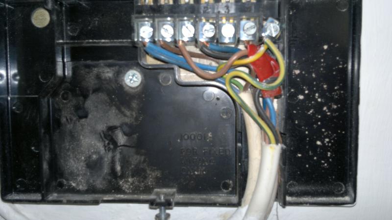
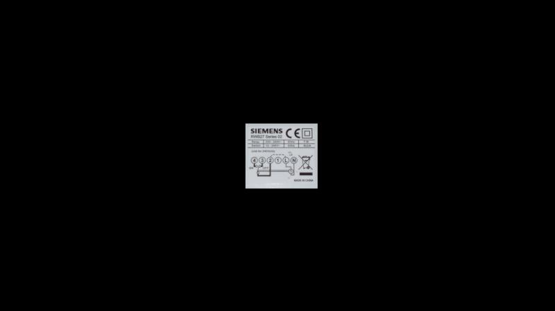
Siemens rwb27 wiring diagram. Summary of contents for siemens rwb27 timeswitch page 1 note. Wiring diagrams for typical tiastar units tool. Only conduit boxes which comply with bs1363 or bs4662 single gang should be used. Wiring of this unit should be carried out by a competent electrician. Page 3 5 siemens industry inc. Wiring diagrams size 1 4.
Siemens motor control center wiring diagrams are at your fingertips within seconds. Rwb27 internal wiring diagram if 240v direct mains switching is required link l to 2. Low voltage switchgear and other power distribution equipment. Whilst every effort is made to ensure accuracy of the instructions given you will appreciate that. If 240v direct mains switching is required link l to 2. All external wiring must comply with current iee regulations.
Rwb27 internal wiring diagram for 240v link between l and 2 the voltage applied to terminal 2 is switched to terminal 4 when the timeswitch is in the on position and to terminal 3 when the timeswitch is in the off position. The backplate can be fitted directly to the wall or onto a conduit box. 3333 old milton parkway alpharetta ga 30005 siemens nema control 87 cut sheet1. Rwb29 internal wiring diagram for more information see enclosed separate wiring and interchange sheet note. The rwb27 is supplied with the industry standard backplate to which the system must be wired. If using the rwb27 to operate the pilot wire of a siemens electric bottom rear of the unit see fig.
Gallery of Siemens Rwb27 Wiring Diagram