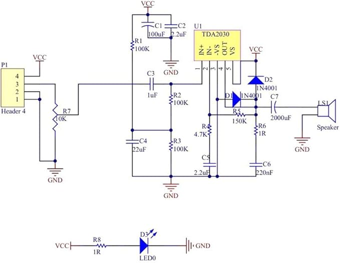
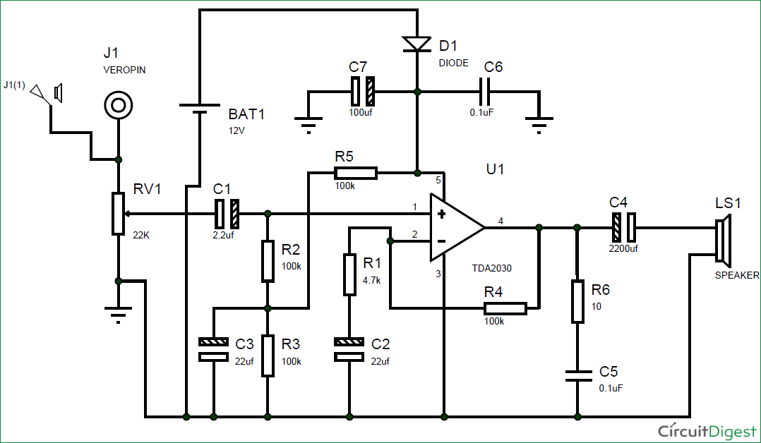
The tda2030 is a powerful audio amplifier ic. We have connected a 22uf capacitor in series to the non inverting pin of the tda2030 here it is acting as the high pass filter.
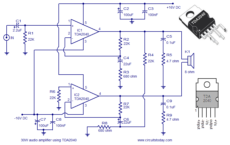
40w Audio Amplifier
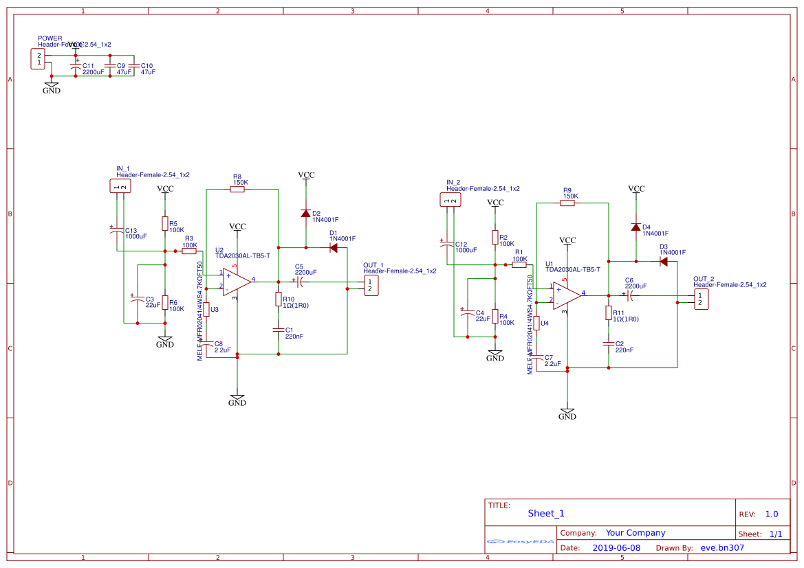
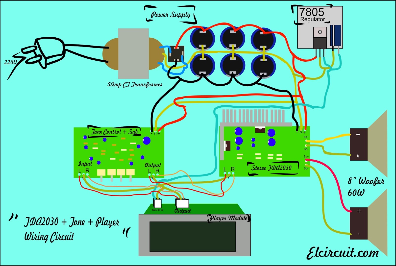
Tda2030 wiring diagram. Audio amplifier circuits can also be made using simple op amps but if you need. So that it allows only the high frequency audio signal. 80 computer subwoofer used this ic. 18wx2 recommended to use 25 4 inch full range speakers 4 8 10 30w europe. Also you can build it easily with the pcb layout. Left and right channels.
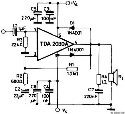
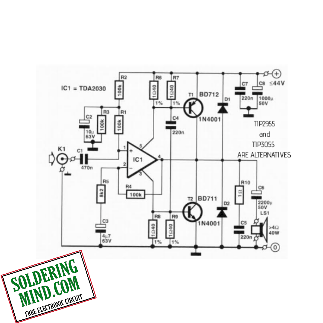
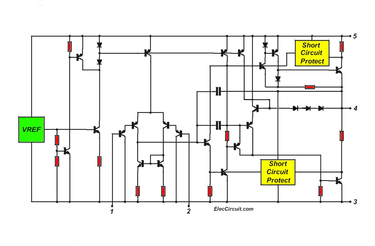
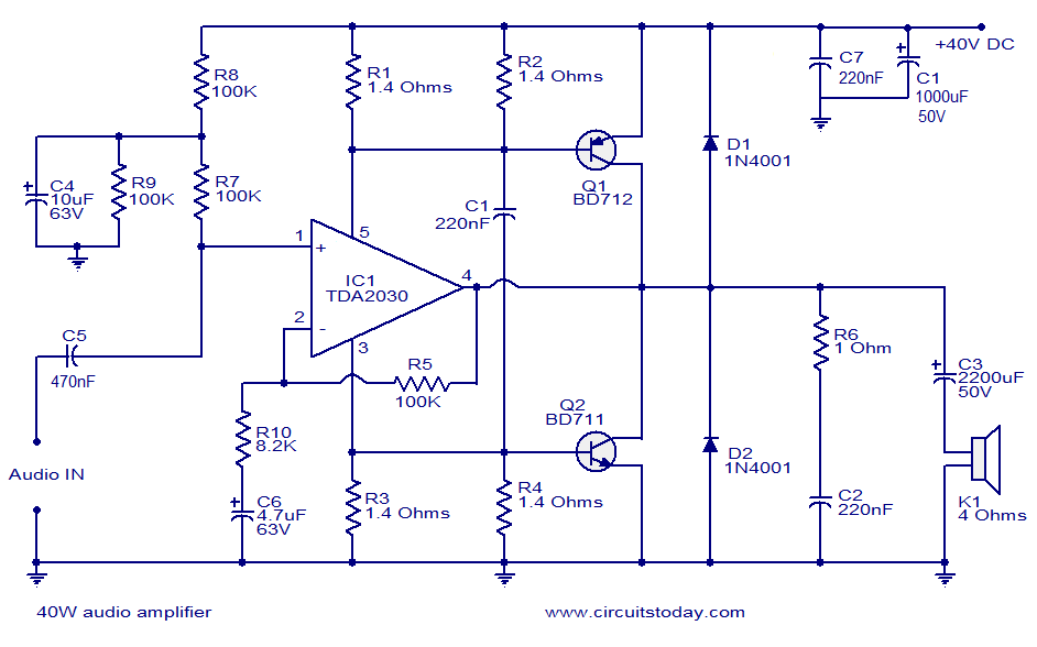
But normally we use 12 volts for good performance. In the above tda2030 circuit diagram the connection of r1 and c2 can be done in series. The op of the ic is connected through the 2200uf value of the series capacitor which allows amplified signal toward the speaker. Through pin 2 of the ic to hold back the noises within the audio signal and pin 3 is grounded. Nowadays tda2030 is a common ic. Tda2030 is a monolithic integrated circuit in pentawatt package intended for use as a low frequency class ab amplifier.
This is an ocl stereo amplifier using tda2030. It is suitable for a small room as the output power of 14 watts 14 watts at 4 ohms speaker. Its a mono based ic. It can run 9 volts to 28 volts. The input sensivity is around 200mv and the amplifier is set by the 47k and 15k resistors. By circuit diagram tda 2030 audio amplifier can output 20 w but in this schematic we have reduced the power to 8w and we use 10w speakers.
Amplifier circuit using tda2030 and tda2050. Not enough bass sound on your subwoofer then try this simple diy circuit to improve your woofer speaker performance. It provides 14w output power d 05 at 14v4ω at 14v or 28v the guaranteed output power is 12w on a 4ω load or 8w on a 8ω. There is a resistor r4 between pin 2 and 4 we called that resistor as feedback resistor. This circuit is constructed by using tda2030 ic and this is intended for use as a low frequency class ab amplifier. The figure is a schematic diagram of the board wiring carefully control wiring.
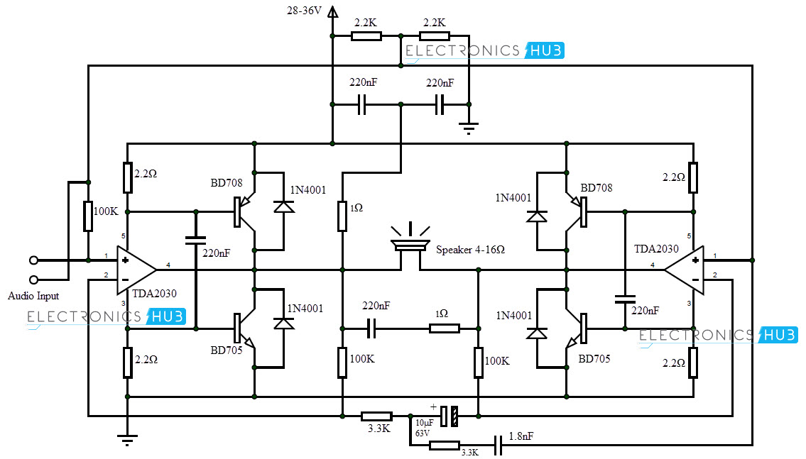
Low price and very easy to make the diagram to make it. Tda2030 10w audio amplifier circuit. We also can use this circuit with the 12 volt battery. Above is the circuit diagram for this tda2030 based amplifier circuit. To boost up the power of the amplifier we need to introduce two transistors in the circuit. We can alter the circuit diagram then we will get up to 50 watts output.
And using a few components with 15 dual power supply for tda2030. This is a low noise and low frequency ic. A single tda2030 ic can deliver up to 15 watts output. An audio amplifier is nothing but one that has the capability to amplify the audio signals from any audio source such as mobile phone jack or microphone so that volume is increased when the audio is played in a speaker.
Gallery of Tda2030 Wiring Diagram