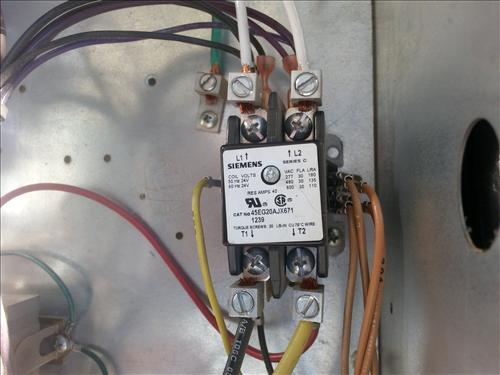
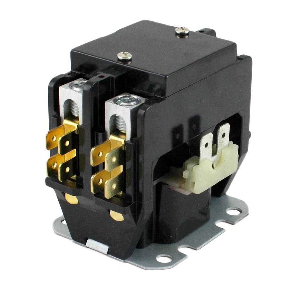
Use these tips to learn how to wire a contactor. Ac contactor control board standard air handler 3 this diagram is to be used as reference for the low voltage control wiring of your heating and ac system.

Sizing The Dol Motor Starter Parts Contactor Fuse Circuit
Ac contactor wiring diagram. How to wire an air conditioner for control 5 wires the diagram below includes the typical control wiring for a conventional central air conditioning systemfurthermore it includes a thermostat a condenser and an air handler with a heat source. Contactor wiring contactor wiring diagram wiring diagram includes numerous in depth illustrations that present the relationship of varied products. Contactors are used to provide this isolation. Always refer to your thermostat or equipment installation guides to verify proper wiring. How to wire an air conditioner for control 5 wires the diagram below includes the typical control wiring for a conventional central air conditioning systemfurthermore it includes a thermostat a condenser and an air handler with a heat source. Collection of contactor wiring diagram ac unit.
Ac contactor control board standard air handler 3 this diagram is to be used as reference for the low voltage control wiring of your heating and ac system. Air conditioner contactor wiring diagram inspirationa wiring diagram. January 14 2019 by larry a. It includes guidelines and diagrams for different types of wiring techniques along with other things like lights home windows etc. Ac contactor wiring diagram. Collection of ac contactor wiring diagram.
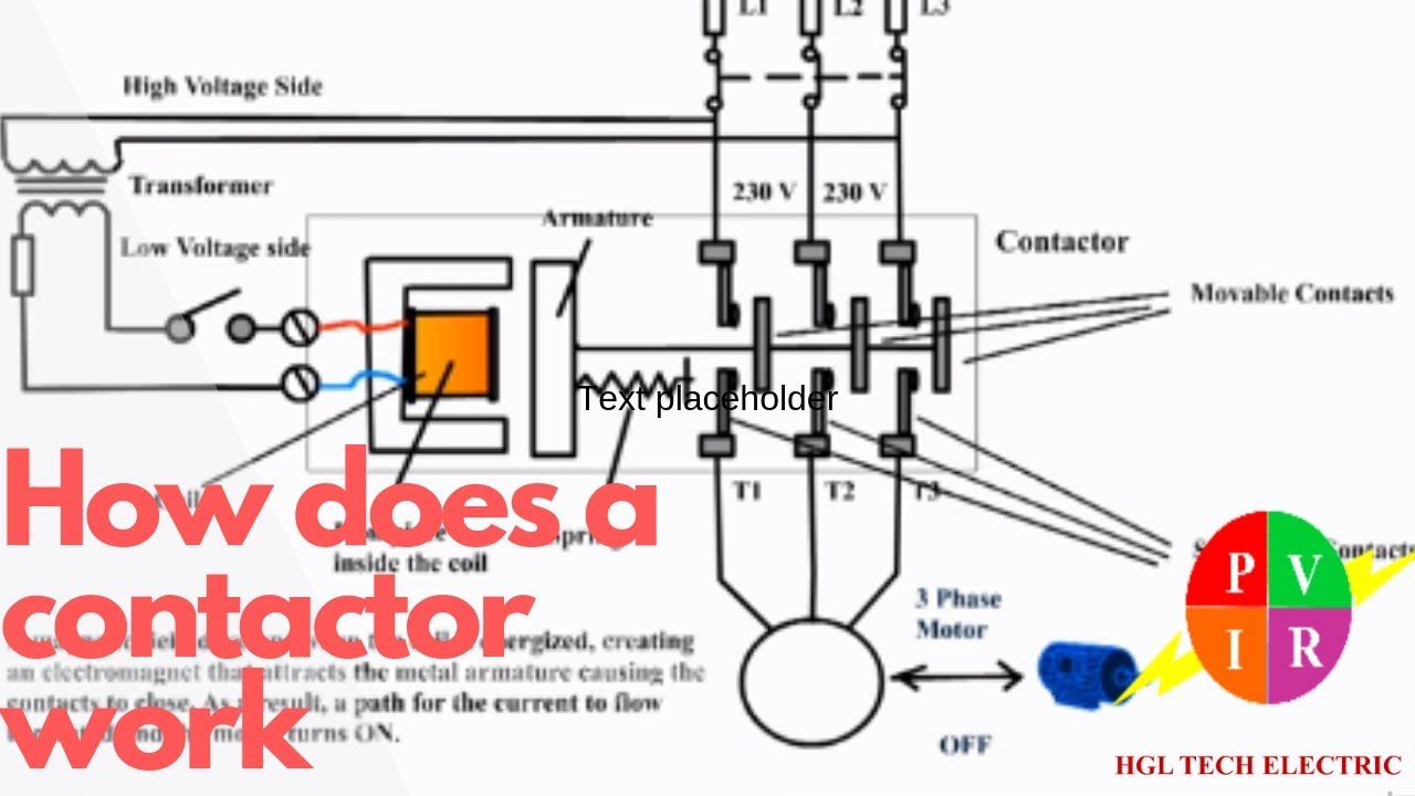
Contactors use 120 volt standard power to energize a magnetic coil which causes a set of internal contacts to close and provide higher power to the equipment. It shows the elements of the circuit as simplified forms and the power and also signal connections between the tools. Moreover the heat source for a basic ac system can include heat strips for electric heat or even a hot water coil inside the. Always refer to your thermostat or equipment installation guides to verify proper wiring. A wiring diagram is a simplified standard pictorial depiction of an electric circuit. These voltages must be electrically isolated from the standard 120 volts ac.
Note some ac systems will have a blue wire with a pink stripe in place of the yellow or y wire. A wiring diagram is a simplified traditional pictorial representation of an electrical circuit. August 17 2018 by larry a. Note some ac systems will have a blue wire with a pink stripe in place of the yellow or y wire. It reveals the elements of the circuit as streamlined forms and the power and also signal links between the gadgets.
Gallery of Ac Contactor Wiring Diagram