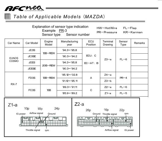
Wiring diagram by model this document describes car models to which the afc neo product code. Complete projects faster and.

Apexi Installtion Instruction Manual S Afc 2 Super Air
Afc wiring diagram. C 819 figure 4. Class a nac wiring requires ca 6075 the end of line resistor is a 51k ohm resistor. Afc neo wiring diagram wiring diagram is a simplified tolerable pictorial representation of an electrical circuit. Afc 50 ins allation manual 5403647 re. Class b nac wiring figure 5. Wiring diagrams from the factory.
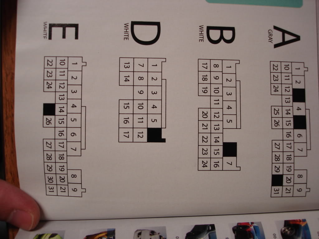
When installing the afc neo both this document and the instruction manual are required. The potter part number for the listed end of line assembly is. The following diagrams view the coupler from the same angle as the diagram. 401 a917 is applicable and ecu terminal arrangement drawings. This helps speed america cable systems extremely durable060 thickness same as junction box which it replaces easy to assemble components easily connect and disconnect from each other secure connections and highest conductivity. Connection diagram for s afc and other equipment 81 nissan 82 toyota 83 mitsubishi.
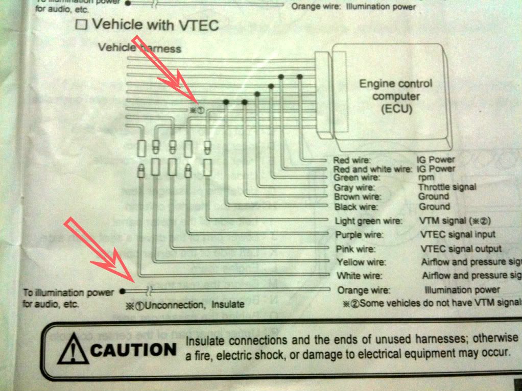
Arc fault circuit interrupter breakers prevent fires by sensing when an electrical arc is about to occur and instantly disconnecting the damaged circuit before the arc builds enough heat to catch firestandard circuit breakers dont always trip in these instances because standard breakers are designed to respond to a sustained amount of heat not a quick surge. Vehicle specific ecu wiring diagram this arrangement of ecu is for only right handle car. Afc offers lengths of ac and mc cable up to 2500 ft in easy to transport barrels. For the operating method and precautions for the afc neo refer to the instruction manual. Refer to page 8 and page 9. Wiring diagram by model this document describes car models to which the afc neo product code.
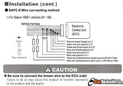
3connect the harness attached to the super afc ii securely to the power cable of the vehicle harness grounding wire engine rpm signal wire throttle signal wire and knocking signal wire from to the ecu by referring to the vehicle specific wiring diagram. Please be careful not to make improper connections or short out the unit. The resistor assembly has been evaluated in past projects and is a standard in the potter panel product line. It shows the components of the circuit as simplified shapes and the knack and signal links between the devices. 401 a017 is applicable and ecu terminal arrangement drawings. When installing the afc neo both this document and the instruction manual are required.
It provides customers with larger traditional put ups while reducing product handling and scrap. Afc has a range of time and labor saving products including pack n roll and mc snapit. Referring to the vehicle specific wiring diagram. For the operating method and precautions for the afc neo refer to the instruction manual.
Gallery of Afc Wiring Diagram