Any particular installation allen bradley inc. 42js visisight 4 3 1 2 3 2 1 4 m12male m8male brown 1 white 2 black 4 blue 3 load load lo do brown 1 do black 4 load load lo transmitted beam emitter brown 1 black 4 blue 3.

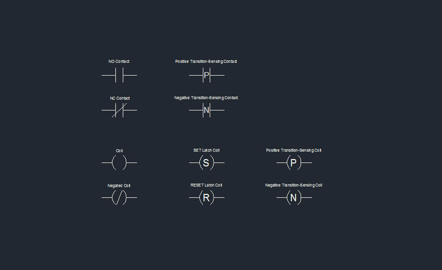
Ladder Diagram An Overview Sciencedirect Topics
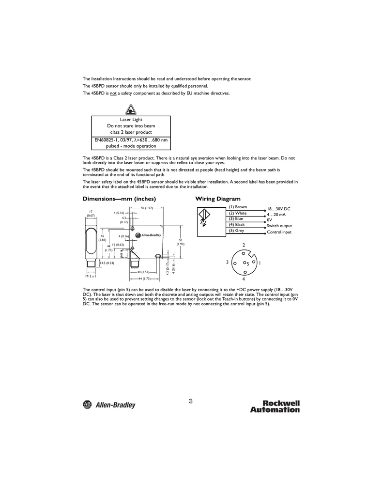
Allen bradley photo eye wiring diagram. Turn sensitivity switch to maximum. Photo eye wiring diagram allen bradley garage door opener pdf. Wiring diagrams cable connections are shown in the following diagrams. Cannot assume responsibility or liability for actual use based on the examples and diagrams. Allen bradley overload heater chart www bedowntowndaytona com pdf. Wiring diagrams ww introduction this booklet has been prepared as a guide to some of the useful ways allen bradleys manual and magnetic across the line starters may be applied.
Photoelectric sensors use a beam of light to detect the presence or absence of an object. This technology is an ideal alternative to inductive proximity sensors when you require long sensing distances or when the item you want to sense is non metal. Allen bradley model 60 2728 wiring instructions connect brown and blue to power. It will also serve as a useful aid where simple wiring systems are to be studied. Light ondark on dklt switch to dark on. Pin numbers correspond to an m12 or m8 male connector on the sensor.
Connect orange common and black normally open to safety reverse. The first section contains the plc io module interface selection tables followed by the swing arm to photoelectric wiring diagrams. The wiring example below displays a wiring scheme of the sick photo eye using an allen bradley 1606 xle power supply and a compactlogix l16er programmable logic controller. To use this manual this manual is divided into two sections. When applying these diagrams it is well to. The controller is equipped with on board io that allows the sensor to be wired directly into the controller without the need of additional hardware.
Doc diagram 944 s2 wiring diagram ebook schematic.
Gallery of Allen Bradley Photo Eye Wiring Diagram