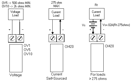
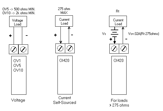
Understanding wiring diagrams analog outputs wiring diagrams for belimo products applications specifications 24 vac transformer line volts 1 com mon 2 hot af24 us nf24 us lf24 us 24 vac transformer 2 to 10 vdc feedback signal line volts blk 1 common red 2 hot wht 3 y 1 input 2 to 10 v 4 y 2 grn 5 output 2 to 10v control. Again the voltage analog output is the easiest one to wire.

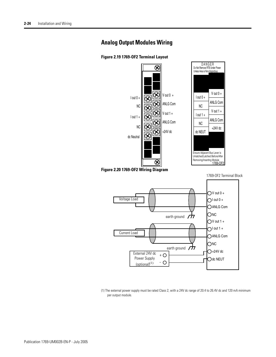
Analog Output Modules Wiring Analog Output Modules Wiring
Analog output wiring diagram. Taking the same vessel described. How to follow an electrical panel wiring diagram duration. Analog inputs in compactlogix duration. Voltage analog output wiring. Analog output module 3 publication 1762 in016d en p june 2013 environment and enclosure preventing electrostatic discharge attention this equipment is intended for use in a pollution degree 2 industrial environment in overvoltage category ii applications as defined in iec 60664 1. Note that these diagrams are without a barrier or isolator fuses and surge protector for keeping it very simple and understandable.
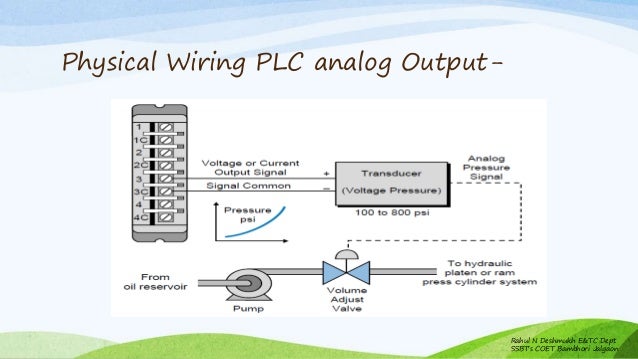
In this article we are sharing the basic concepts of plc and dcs control systems wiring diagrams for digital input di digital output do analog input ai and analog output ao signals. Wiring 1768 l43 inputoutput cards duration. For this you will only need 2 wires. The device you connect to your analog output is what decides which type of analog signal you should be using. Plc wiring diagrams guide include the discrete signals wiring plc digital input modules wiring plc output modules wiring and basics of plc terminations. Plc analog signals wiring techniques plc tutorials unlike the discretedigital onoff circuit analog signals vary across a range of voltage or current.
If you want to control a valve with a 4 20 ma signal then your analog output should also be 4 20 ma.
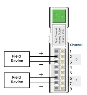
Gallery of Analog Output Wiring Diagram