6 do not print beyond page 6 pages 5 8 kept for illustrations only. Thermostat wiring the thermostat operation switches the 12vdc to all output terminals 7b.

Duo Therm Rv Thermostat Wiring Diagram Diagram Base Website
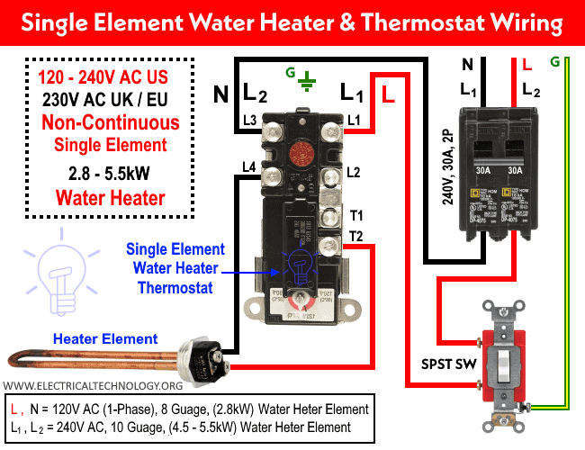
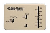
Analog thermostat wiring diagram. A wiring diagram is a type of schematic which makes use of abstract pictorial symbols to show all the interconnections of parts in a system. Duo therm thermostat wiring diagram duo therm ac thermostat wiring diagram duo therm analog thermostat wiring diagram duo therm comfort control thermostat wiring diagram every electrical arrangement is composed of various distinct components. For most up dates and recent news about best of dometic analog thermostat wiring diagram pics please kindly follow us on tweets path instagram and google plus or you mark this page on bookmark area we try to present you up date periodically with fresh and new pics love your surfing and find the perfect for you. Wiring diagram for 3107541017 cool furnace heat strip wiring diagram for 3107541009 cool furnace wiring diagrams. Dometic analog thermostat wiring diagram. Analog control kits used with air conditioners for cool and furnace cool furnace and heat strip.
1 thermostat analog 3106995032 3106995057 3106995040 2 screw m 14 20 x 800 4 req 3106756020 3106756020 3106756020. If not the structure wont function as it ought to be. Rc red wire power 24 vac rh or 4 red wire jumpered power 24 vac w white wire for heating enable y yellow wire for cooling enable. The basic heat ac system thermostat typically utilizes only 5 terminals. Each component should be set and connected with other parts in specific way. The diagram below shows how a basic 4 wire thermostat is connected as indicated by the color code chart above.
Gallery of Analog Thermostat Wiring Diagram