Internal switch wiring diagram with valve in normally open position figure 4 model bfv 300c butterfly valve internal switch wiring diagram with valve in normally closed position. 2 mount the mgo lav to the stub end butterfly valve.

Anvil Cross Black Cast Iron 125 3 4 In Npt 0300108800
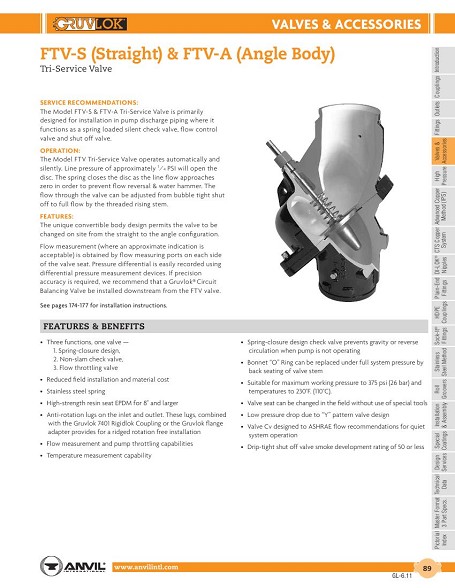
Anvil butterfly valve wiring diagram. One is wired for. The valve is supplied with two internal switches. Rugged enough to take the punishment yet the series 7600 valve is light in weight for easy handling and installation. The valve is designed and manufactured to meet or exceed the requirements of mss sp 67. The valve is rated at 300 psi for steel pipe in the 2 to 10 sizes. The gruvlok figure an7722 3a grooved end butterfly valve is ul listed and fm approved as a system control valve.
4 open and close the valve with the hand wheel checking to ensure smooth operation. Tfp1511 page 5 of 8 8 inch dn200 10 inch dn250 6 inch dn150 3 inch dn80 4 inch dn100 2 12 inch dn65. The valve is supplied with two internal switches. The gruvlok figure an7722 3a grooved end butterfly valve is ul listed and fm approved as a system control valve. The 2 through 10 sizes are agency rated for both indoor and outdoor service. 3 back off both of the stop bolts on the mgo lav.
The 2 through 10 sizes are agency rated for both indoor and outdoor service. Every valve is seat tested to 110 of rated pressure. The series 7600 valve is rated 200 psi 138 bar to full vacuum at temperatures from 0 to 150 f 178 to 656 c. Not intended for use in potable water systems. For data on fire protection listingsapprovals contact your anvil representative. The valve is rated at 300 psi for steel pipe in the 2 to 10 sizes.
The valve body is a rugged one piece casting with an integral mounting base for gear operator or handle actuation while providing room for a minimum of 2 of pipe insulation. 1 use only butterfly valves that have been tested for seating torque and fall into the approved torque range for each actuator size.
Gallery of Anvil Butterfly Valve Wiring Diagram