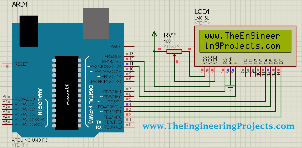
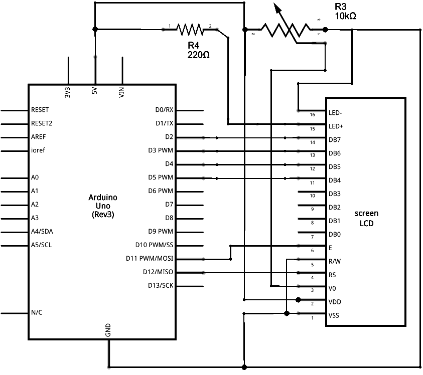
In the case where the lcd is powered with the arduino by the 5v usb cable selecting the contrast resistor to be 2k ohm and the back led resistor to be 100 ohm is a good start. Follow the diagram below to wire the lcd to your arduino.
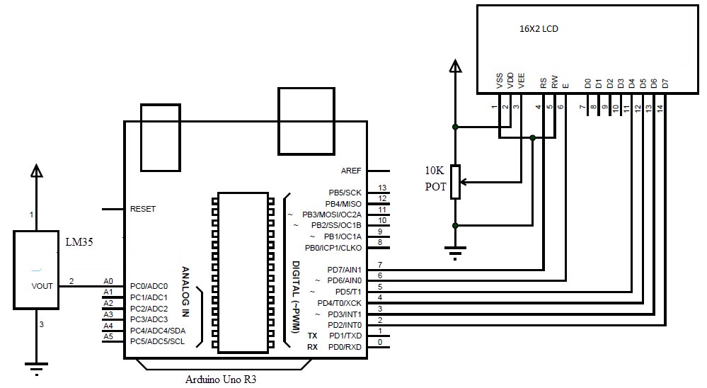
Arduino Based Digital Temperature Sensor Arduino Project Hub
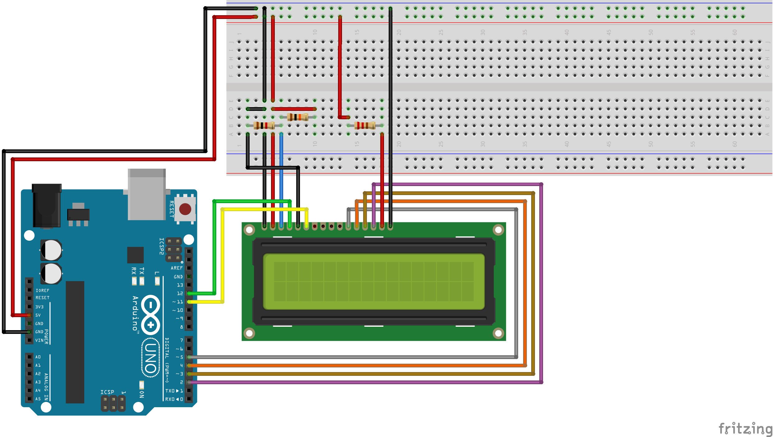
Arduino lcd wiring diagram. Db7 is pin 14 on the lcd and it connects with an orange wire to arduino 12. Lcd rs pin to digital pin 12 lcd enable pin to digital pin 11. If you happen to be better reading that looking at diagrams lets go over the pinouts in detail. We will be using the lcd in 4 bit mode this means you dont need to connect anything to d0 d3. Next are the remaining 3 data lines db6 pin 13 yellow db5 pin 12 green and db4 pin 11 blue which we connect to arduino 11 10 and 9. The potentiometer is used to adjust the screen contrast.
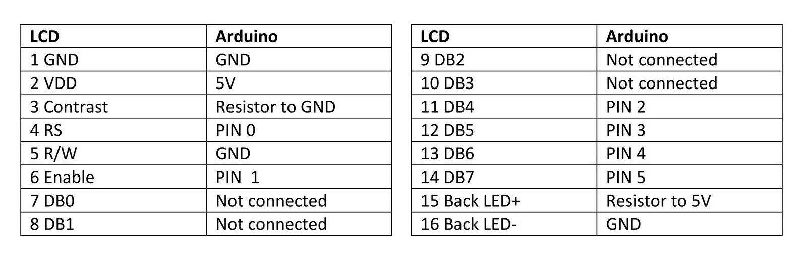
Thanks to the magic of fritzing one of my favorite tools for drawing wiring diagrams you can see my wiring schematic. Alternatively a 5k potentiometer can be used to adjust the contrast for vest viewing. Component pinouts in detail. The table below explains how to connect the lcd pins to the arduino. Once you have wired everything we can start programming the lcd. The resistor in the diagram above sets the backlight brightness.
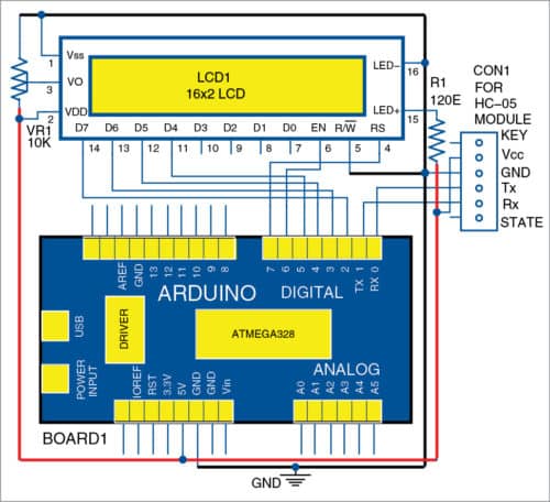
To wire your lcd screen to your board connect the following pins. Smaller resistors will make the backlight brighter. 162 lcd with arduino wiring diagram. A typical value is 220 ohms but other values will work too. Arduino lcd wiring diagram. The rw pin is connected to ground this will pull the pin low and set the lcd to write mode.
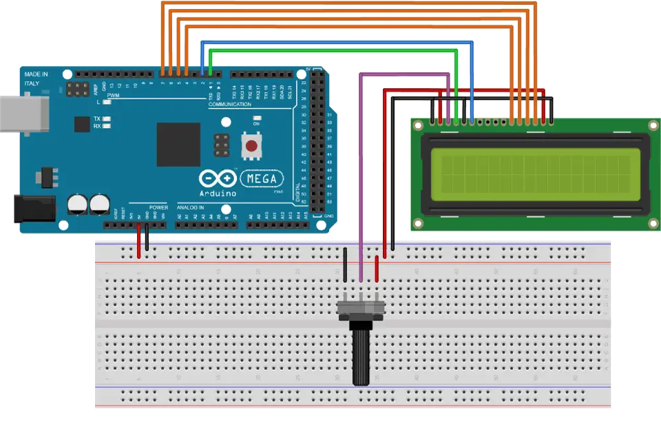
Before wiring the lcd screen to your arduino or genuino board we suggest to solder a pin header strip to the 14 or 16 pin count connector of the lcd screen as you can see in the image above.
Gallery of Arduino Lcd Wiring Diagram