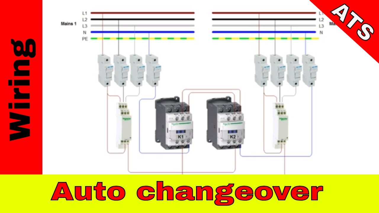
When there is a power failure on mains 1 the pfr will open. May 2018 om manual for 600 1000a 480 vac 3 position open service entrance contactor based transfer switch figure 3.
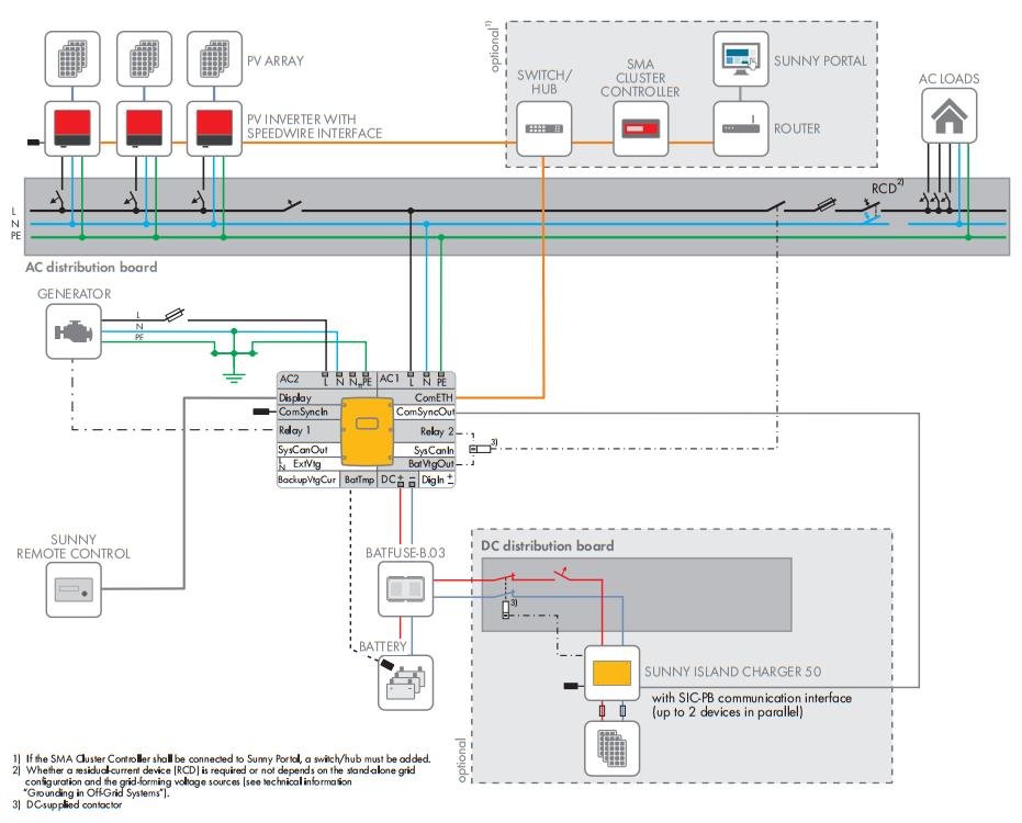
Generator Settings On The Sunny Island For Off Grid Systems
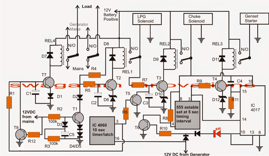
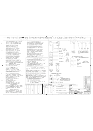
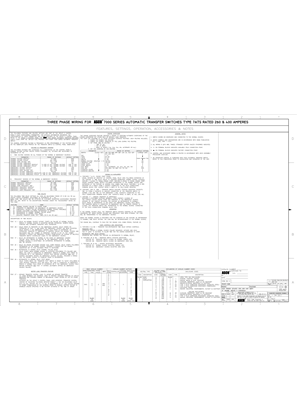
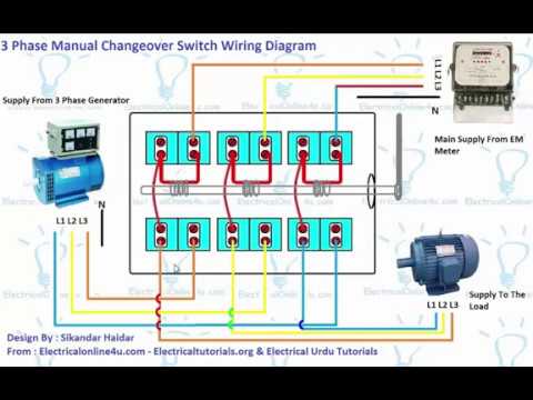
Ats wiring diagram 3 phase. Four main panels comprise. Wiring diagram asco series 300 group g automatic service entrance transfer switch atsntsaus 30 230 amps frame d three phase 978741 document number ts wd 300dats978741. Kohler ats wiring diagram 89 related diagrams pravoslavnic electricitate. Current flow is again shown through the a phase only to simplify the diagram. In this video you will find out how to use phase failure relay in simple auto changeover application. Electrical panel wiring electrical circuit diagram electrical projects electrical installation electronic engineering electrical engineering diy electronics electronics projects arduino.
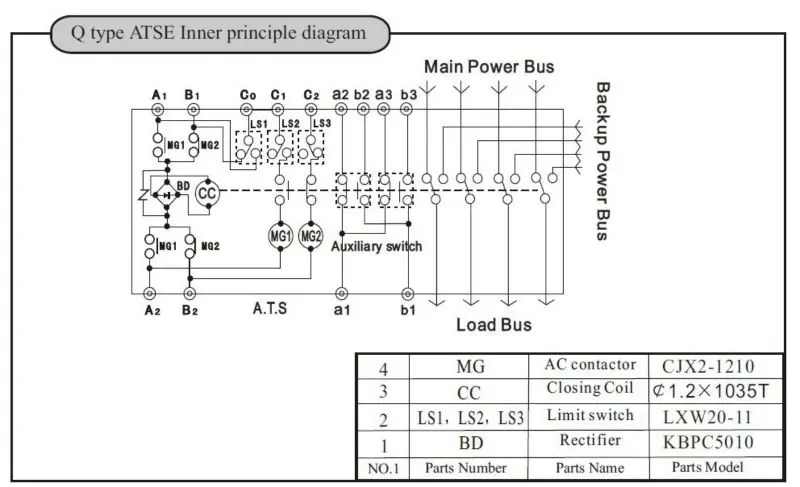
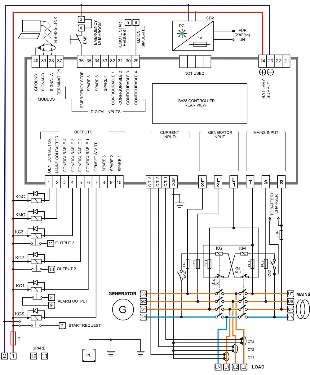
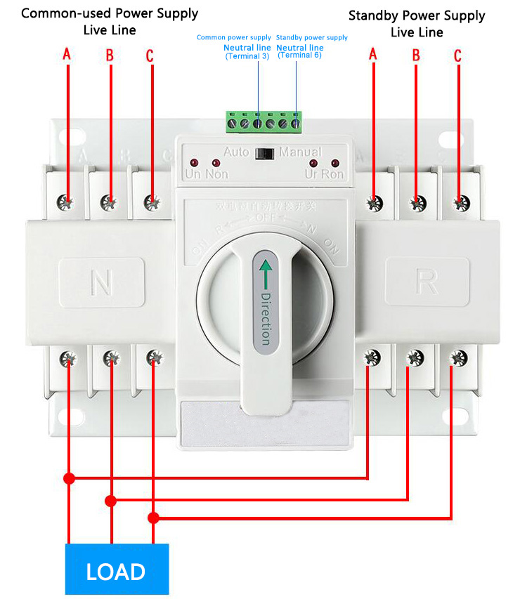
The idea of the system is simple. Power systems topics 107 selecting between a three or four pole ats 4 switched neutral diagram a b c n n a. Ats port configuration wiring diagram for both 3 phase single phase connecting up 230v single phase using zneutral and zl1 common connect up incoming and output as indicated in the above illustration. Auto transfer switch wiring diagram wiring diagram radixtheme. Ats wiring diagram for standby generator collections of generac ats wiring diagram download. 316 120 10 732 150 12 14 200 17 516 275 23 38 375 31 12 500 42 916 600 50 table 3 tightening torque for bus bars bolt size torque bolt grade 5 lb.
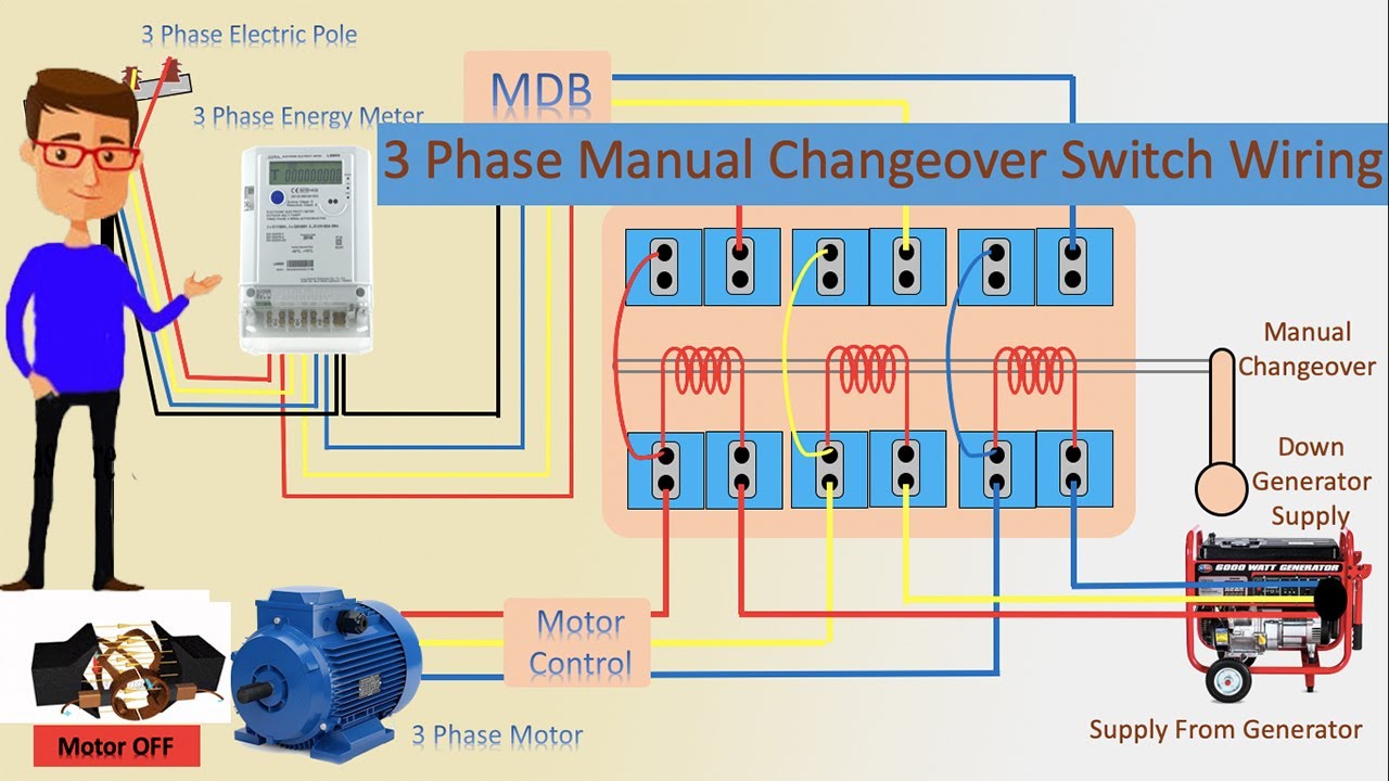
Wiring diagram asco series 300 automatic transfer switch ats 30 230 amps frame d single phase 718516 asco series 30. Three phase electrical wiring diagram. How to install three phase automatic transferchangeover switch fig 5 shows 4 poles 3 phase automatic transfer switch ats connection to the main distribution board. Wiring diagram standby generator best wiring diagram for a generator. Figure 3 depicts a power system with the normal source utility powering the loads through a four pole ats switched neutral with a ground fault present. The eaton contactor based ats is designed with easy installation and simplified maintenance in mind.
14 20 72 6 516 18 132 11 38 16 300 25 12 13 720 60 power connections zenith transfer switches are supplied with ul listed solderless screw type terminals. Generac ats wiring diagram download. All the wiring connections are same as above for manual operation of three phase changeover switch but the switching operation is automatic. Typical service entrance open transition ats. No other wires should be connected otherwise the ats switch will not work.
Gallery of Ats Wiring Diagram 3 Phase