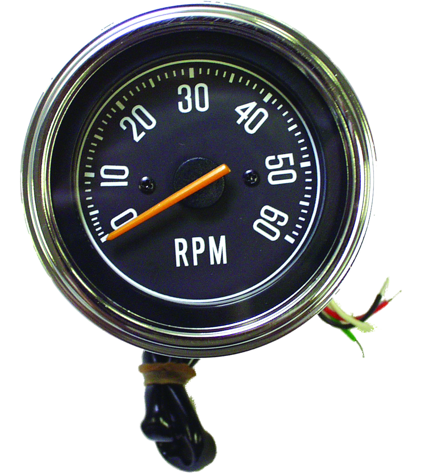
Connect this red wire so that when the car is started the tachometer will begin operating. When used on 05 1 or 15 pulse per rev ignitions a brief pause in pointer movement may be observed as rpm is rapidly decreased.
How To Install A Tachometer Onallcylinders
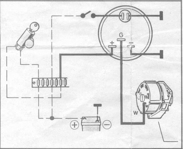
Auto gauge rpm wiring diagram. The tachometer is designed to show the engine rpms or rotations per minute. Turn the power off. Tachometers with two or three buttons use an advanced microcontroller circuit to measure engine rpm for increased accuracy and zero pointer flutter at low rpm. Stop when it reaches the desired shift point. The auto meter 2888 and 3788 diesel tachs will work out of the box with your diesel engine. Turn on the power to the tach.
Warrants to the consumer that all auto meter high performance products will be free from defects in material and workmanship for a period of twelve 12 months from date of the. It contains directions and diagrams for various varieties of wiring strategies along with other things like lights windows etc. Horsepower for example 3400 rpm. The tachometers in the diagram use a specific auto meter wiring color code so if youve got a different brand of tachometer you should reference its own schematic. The wiring diagram shown is a typical installation. To operate the auto gage shift lite tachometer first determine your engines shift point for max.
Depending on your engine there may be a constant flow wire and a pulse wire to the tach as well as the additional wires for the ignition lights and other components. Auto meter products inc. Set the desired rpm by turning the adjust knob on the back of the tach the pointer will move. T splice wire adapters allow for new wires to be spliced together with existing ones using pressure connectors that you squeeze around the existing wire to make the connection. Its important to make sure youve got the correct wire for the tachometer which means you might need to use a multimeter with a tach setting to test the wires correctly and. Autometer has designed their tach to be used with four six.
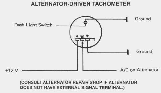
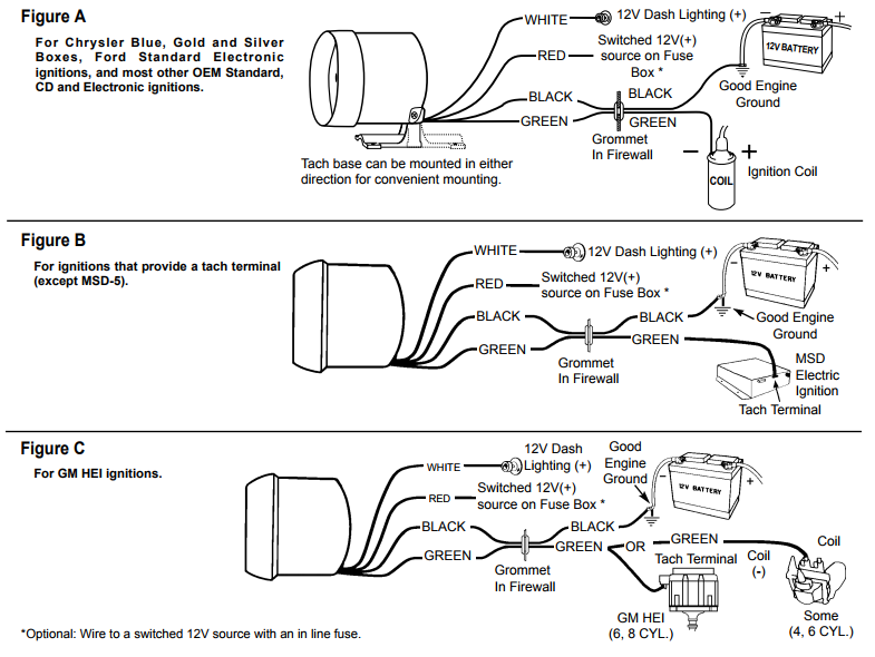
Wiring green white red. Rpm x1000 by 180. The red wire is for the ignition switch. It includes diagrams for common ignition systems including those used by general motors ford and chrysler plus many aftermarket manufacturers. Auto gauge tach wiring wiring diagram data autometer gauge wiring diagram wiring diagram consists of numerous in depth illustrations that show the connection of varied items. Once you have selected a mounting location you can run the four wires that operate the tachometer.
Wiring your new autometer tachometer into your car will complete the installation. Using a small inductive pickup strapped to the alternator these units are easily calibrated to read rpm quickly and accurately just as youd expect from and autometer tach. Thanks to our temporarily mounted auto meter tach when the day was done we jumped on the freeway and knew our engine never revved over 2000 rpm at highway speeds despite a set of 373 gears. For chrysler blue gold and silver boxes ford standard electronic.
Gallery of Auto Gauge Rpm Wiring Diagram