December 12 2018 by larry a. A wiring diagram is a simplified traditional pictorial depiction of an electrical circuit.

Generator Ats Wiring Diagram Ats Panel Genset Controller
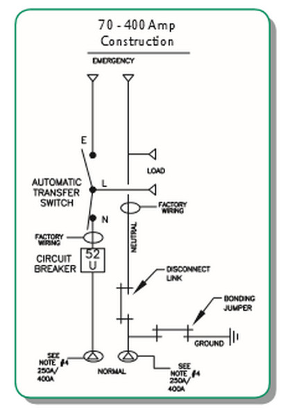
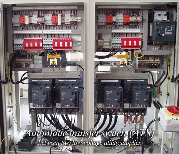
Automatic transfer switch wiring diagram. Although the original branch circuit breakers are no longer used you can leave them in place as spares or remove two of them to make space for the new double pole 60a breaker. This transfer switch is suitable for use as service equipment. These switches figure 11 are used with a single phase system. Standard diagrams transfer between 3 sources 2 bus bars continued implementation compacity built in solution plug and play mechanical and electrical interlocking are in build operation only 2 or 3 emergency handles instead of 4 or 5 a motorized switch can be added on the non critical loads for optional disconnection. Wellborn variety of 200 amp automatic transfer switch wiring diagram. It reveals the elements of the circuit as simplified forms and the power as well as signal links between the tools.
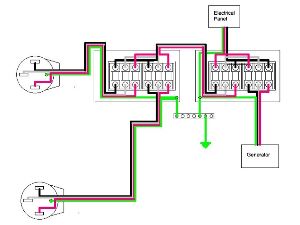
Use the transfer switchs wiring harness to connect the unit to the circuit breaker. The transfer switch consists of a transfer mechanism utility service disconnect circuit breaker a control relay fuses ter minal strip and fuse holder for connection of sensing wires. They should join the circuit breaker through a knockout found at the bottom of the box. Click on picture for larger view. 800 x 600 px source. Figure 4 wiring diagram of a manual transfer switch in the off position figure 5 wiring diagram of a manual transfer switch in the on.
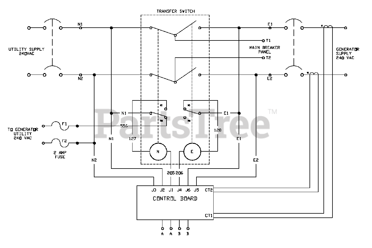
A wiring diagram is a simplified standard pictorial depiction of an electrical circuit. Cutler hammer automatic transfer switch wiring diagrams directions for use the drawing package can be used a s a point to point wiring diagram for maintenance and diagnostic purposes for solid state logic spb transfer switches all voltages. The wires should be drawn through 1 of 3 knockouts located on the underside of the switch. Many systems do not switch the neutral wire and tie the three neutral wires together. Assortment of generac 200 amp automatic transfer switch wiring diagram. Carlplantme here are a few of the top illustrations we get from various sources we wish these pictures will work to you and also hopefully really pertinent to what you desire about the diagram of automatic transfer switch wiring is.
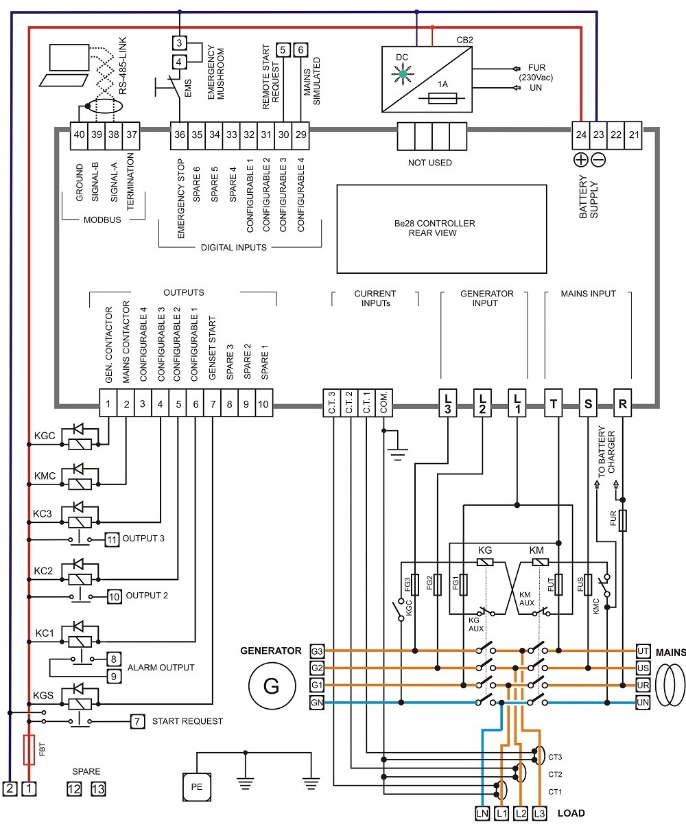
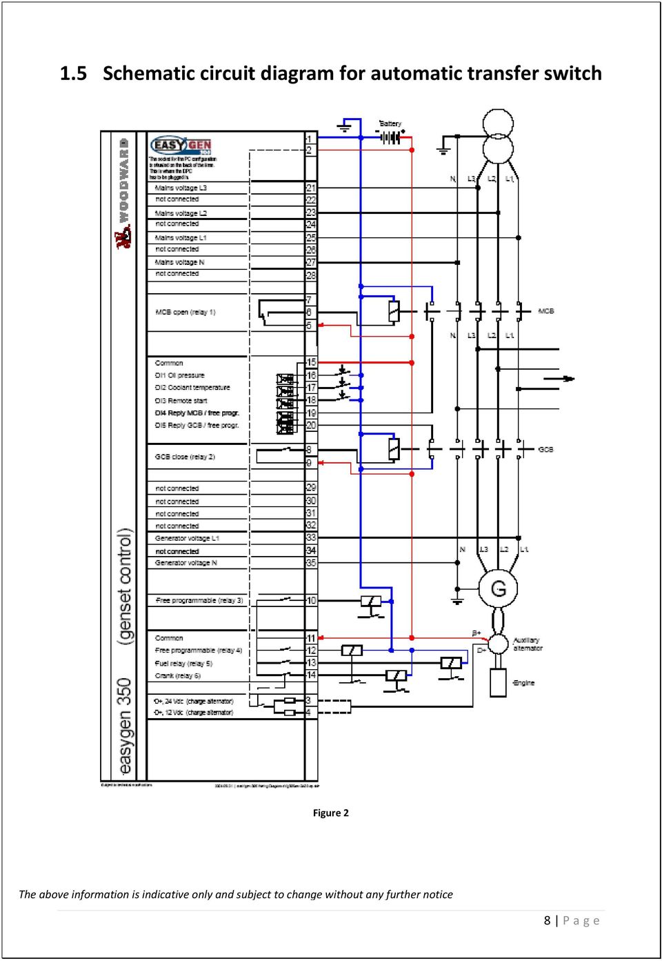
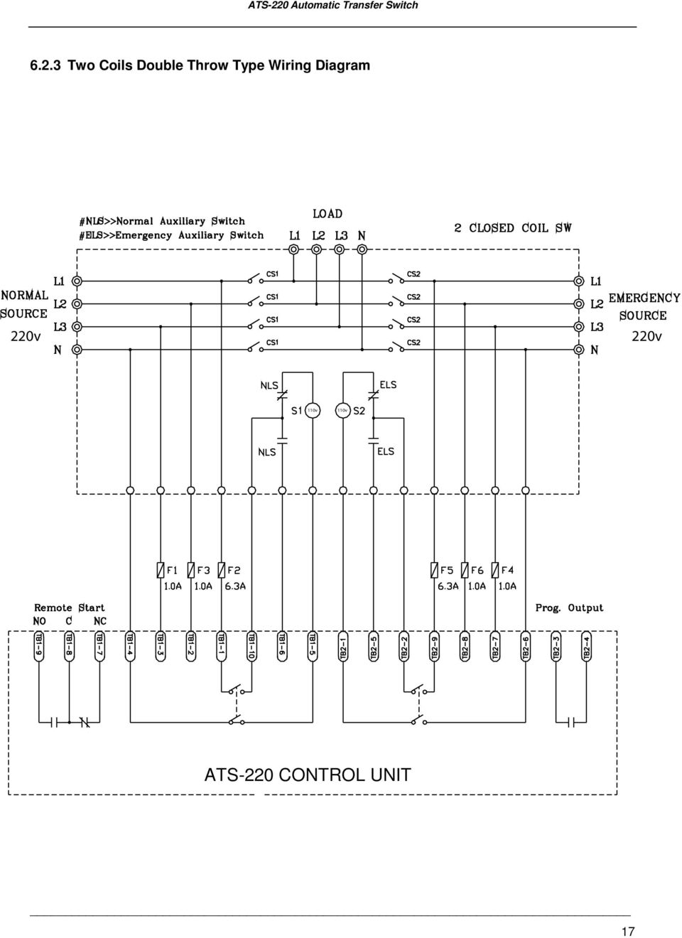
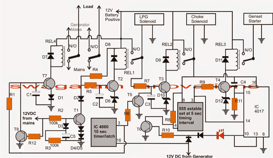
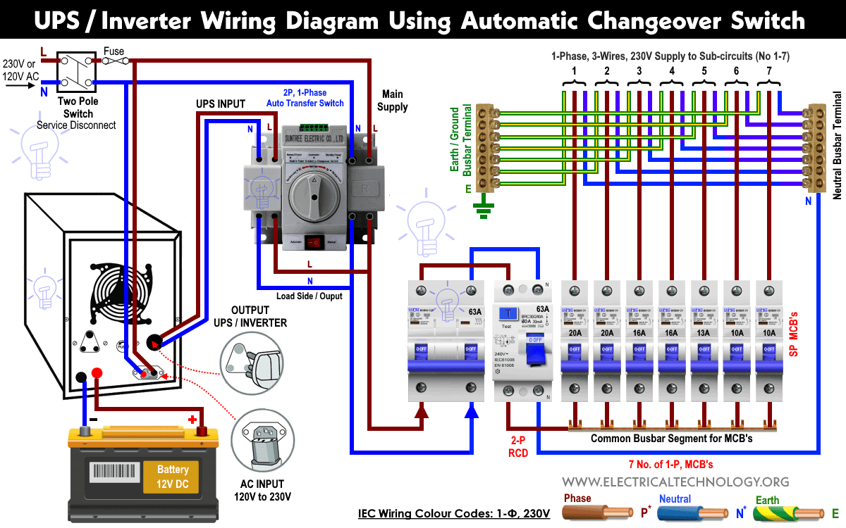
It is also shows the working and operation for different changeover switches wiring connections like single phase manual changeover switch with generator three phase manual transfer switch connection with generator as well as single phase and three phase automatic transfer switches connections to the 1 and 3 phase generators and main fuse board. Automatic transfer switch wiring diagram free to be28 controller size. It reveals the components of the circuit as simplified forms and also the power and signal links between the gadgets. A wiring diagram usually provides info concerning the relative position as well as setup of tools as well as terminals on the devices to assist in structure or servicing the tool. Verify the method of wiring with your transfer switch and generator before installation. The wiring harness is preterminated in the selective circuit transfer switch so the only connections that have to be made are those in the service entrance panel.
Gallery of Automatic Transfer Switch Wiring Diagram