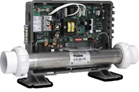
Wiring diagram for balboa vs500z circuit board 54369 wiring diagram. 1 55 kw stainless steel heater assembly m7 heater assembly included.
Bp2000 Troubleshooting Testing Fuses
Balboa vs500z wiring diagram. The white wire is for common connection and the green wire is for ground. The plug will only fit one way. Safety ti p s keep children and pets away. Following the wiring diagram that is provided. Refer to the wiring diagram to verify the correct wiring of the control system. See the ratings table on the wiring diagram attached to the cover of the enclosure for the configured voltage.
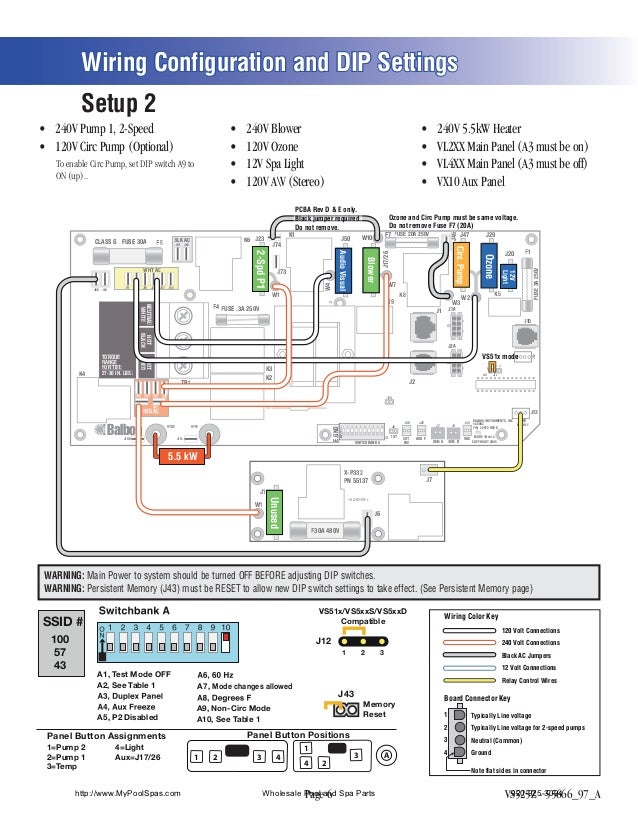
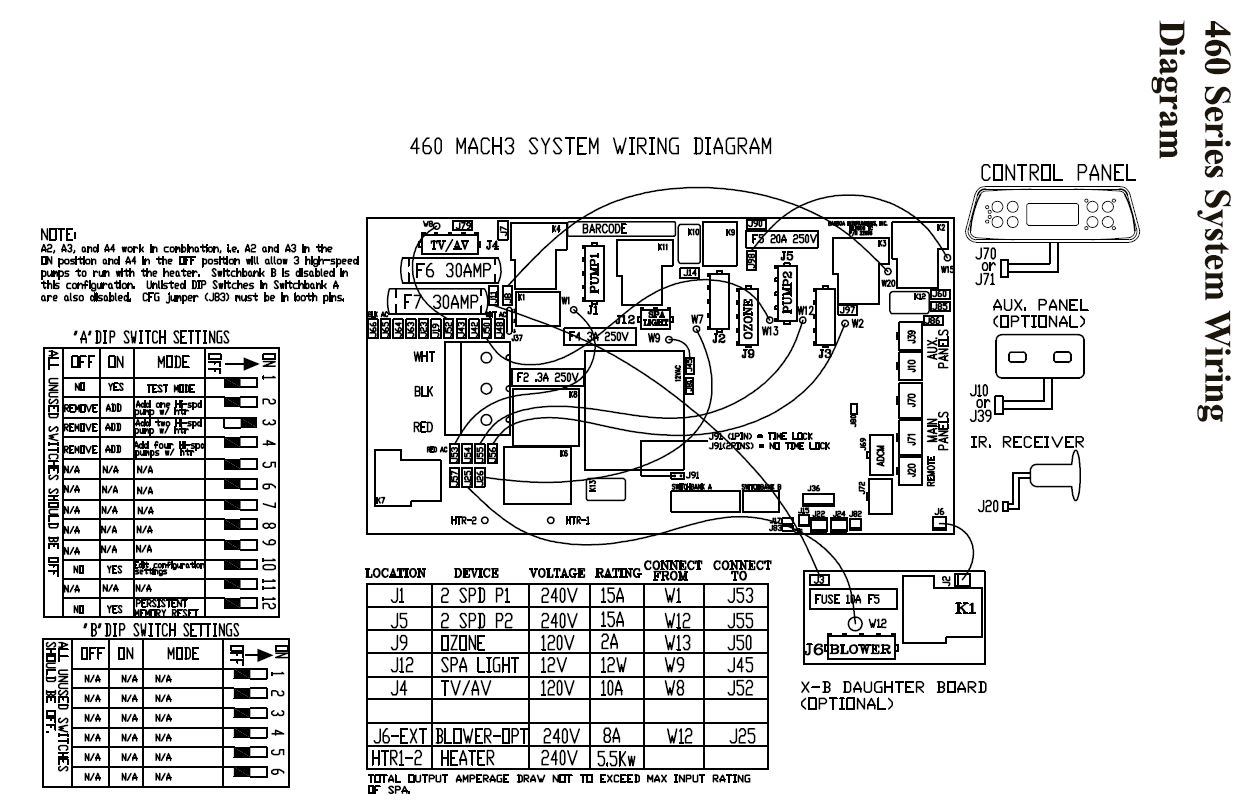
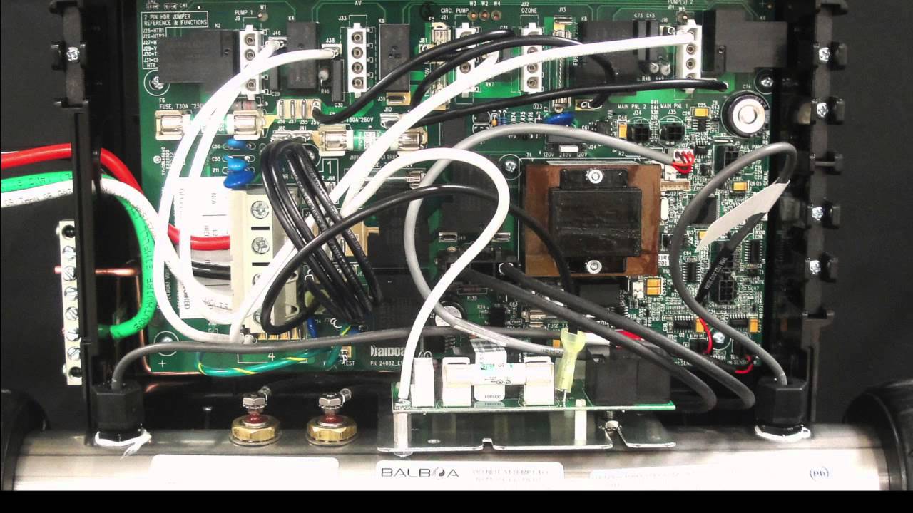
Wiring configuration and dip settings setup 1 as manufactured s 60ump 3peed s 6lower s 6zone s 63paight. I searched and found a wiring diagrams online for it it was wired for 120 therefore would not let my pump run. For 240v output w2 connects to red ac and for 120v output w2 connects to white ac. See the ratings table on the wiring diagram attached to the cover of the enclosure for the configured voltage. Connect the ozone cord in the ozone location j29 on the circuit board. Of the electric supply panel use this diagram for voltage measurement points and with a continuous green for proper reconnection of wires.
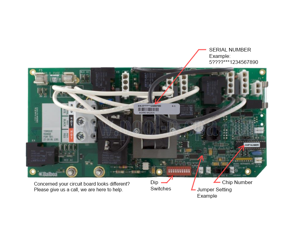
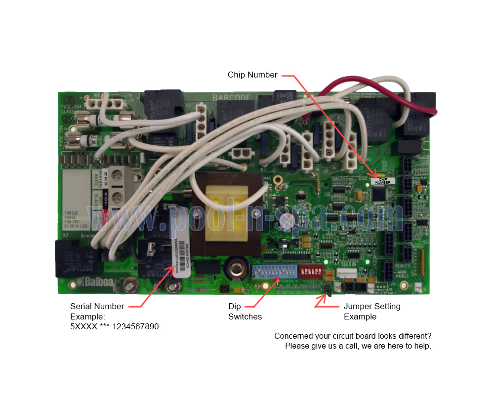
B vac w1 w7 w1 j1 j2 w2 w3 g c w4 k4 k2 k3 balboa. Vs500z pn 22972 rev d made in usa copyright 2005 s1 j6 j7 j8 j44 j60 j22 u4 htr2 htr1 j100 j101 tb1 fuse 3a 250v fuse 20a 250v fuse 3a 250 v egn d f4 k6 k10 k1 k8 k9 k5 j23 j74 j73 j46 f1 j47 j29 j5 0 f7 j 17 2 6 j20 j1a j10 j13 j2a ext. I m p o r t a n t be sure to bring the correct circuit board topside control panel components and tools. The ozone cord will have 3 wires. Always refer to the wiring diagram which is included with each system on the inside of the system box cover. Ozone connector voltagethe vs500z circuit board is factory configured to deliver a preset voltage 120v or 240v to the on board ozone connector j29.
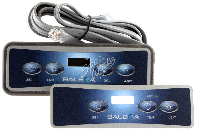
Operation manual for the balboa brand vs500z and vs501z series. There were no directions as to how wiring should be. The black wire is for line 1. Balboa vs500z circuit board 54369. Vs500z pn 22972 rev d made in usa copyright 2005 s1 j6 j7 j8 j60 j22 j44 u4 htr2 1 j100 j101 tb1 fuse 3a 250v fuse 20a 250v fus e 3a 250v egn d class g fuse 30a f5 f4 k6 k1 k8 k9 k5 j23 j74 j73 j46 f1. Balboa vs500z spa control system complete 54219 z the balboa vs500z control system can operate.
Uêif everything looks to be in perfect working order then the gfci. Tripping problems can be attributed to incorrect wiring. The risk of electrical shock connect this terminal always refer to the wiring diagram which is included to the grounding terminal with each system on the inside of the system box cover. For 240v output w2 connects to red ac and for 120v output w2 connects to white ac. The vs500z circuit board is factory configured to deliver a preset voltage 120v or 240v to the on board ozone connector j29. Troubleshooting usually finds the problem.
Keep in mind that a majority of gfci. Use this diagram for voltage measurement points and for proper reconnection of wires.
Gallery of Balboa Vs500z Wiring Diagram