It shows the elements of the circuit as simplified forms and also the power as well as signal links in between the gadgets. Cable entry 2attach the paper stencil onto the.
Example Dsc Security System Burglar Alarm System
Beam detector wiring diagram. The d1 d2 is for 24vdc power supply. The beamsmk allows system sensor reflected beam detectors to be mounted when surface wiring is used. For us installations it is typically a short circuit. This is the basic fire alarm system used in household wiring. Optical beam smoke detector. This kit must be used when mounting the trans.
According to the wiring diagram. Projected beam smoke detector 3825 ohio avenue st. Diagram to avoic interference between beams. The units detect intruders only when both upper and lower beams are simultaneously interrupted preventing nuisance alarms due to fallen leaves etc. A wiring diagram is a streamlined traditional pictorial depiction of an electrical circuit. Note 1 this component is the fire resistor and its value is specified by the fire control panel manufacturer.
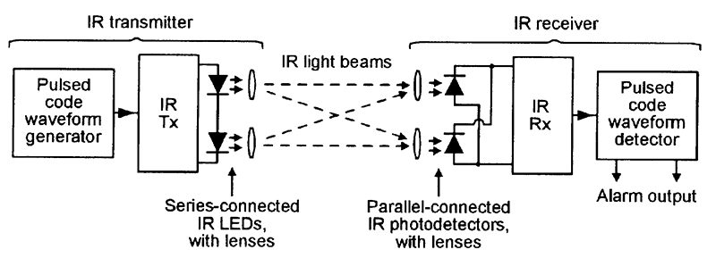
Wired infra red beam detectors adb range 9 8 1 0 tamper switch relay contact output nonc contact rating acdc30v 30mamax model. A trouble is signaled to the fire panel once the battery life is exceeded. In our basic wiring diagram a single or multiple heat and smoke detectors are installed in the home by connecting the live line or hot neutral ground and an interconnected wire to the alarm. Wiring diagram for connection of a single conventional detector to a zone. A smoke or heat detector can be installed to the existing or new home wiring. The nr40tx and nr80tx are beam detectors designed to provide an alarm relay activation upon detection of an intruder moving through a pair of invisible pulsed infrared beams.
Wiring the wired ir beam sensor to wired gsm alarm system. 3put the cable through the hole for wiring. Parts diagram not to scale. Charles illinois 60174 800736 7672 fax. Assortment of through beam photoelectric sensor wiring diagram. 5 wiring 16 51 wiring a single detector 16 52 wiring a remote indicator 17 53 wiring multiple detectors 18 6 setup 20 61 preliminary alignment 20 62 fine tune alignment 22 7 troubleshooting 25 71 transmitter 25 72 receiver aim mode cover off 25 73 receiver normal mode cover on 25 8 maintenance and testing 27 81 fire alarm reset 27.
Terminal block paintable trim ring c1049 00. Six pulses imager cannot discern the signal from the emitter beam due to an oversaturation of light. The z1 z2 for loop. The sensor consists of transmitter and receiver. The ir beam sensor is the one of professional security equipment to provide perimeter protection it creates invisible fence around your premises. Smoke detection continues to function while there is sufficient residual battery power.
Beam detector i 9105r mounting the detector the intelligent beam detector should be. For conventional system k11k12 for fire output normally open and k21k22 for fault output normally close. We herein provide the wiring diagram as below.
Gallery of Beam Detector Wiring Diagram