Circuitry layouts are comprised of two points. A wiring diagram is a type of schematic which uses abstract pictorial symbols to demonstrate all the interconnections of components inside a system.
Design Guide For 12v Systems Dual Battery Systems Solar
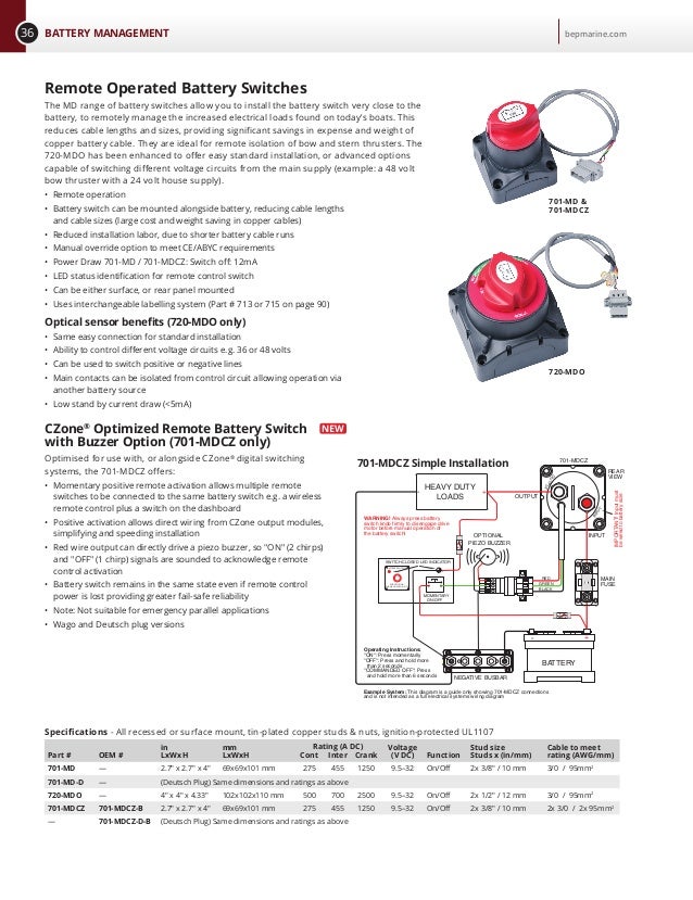
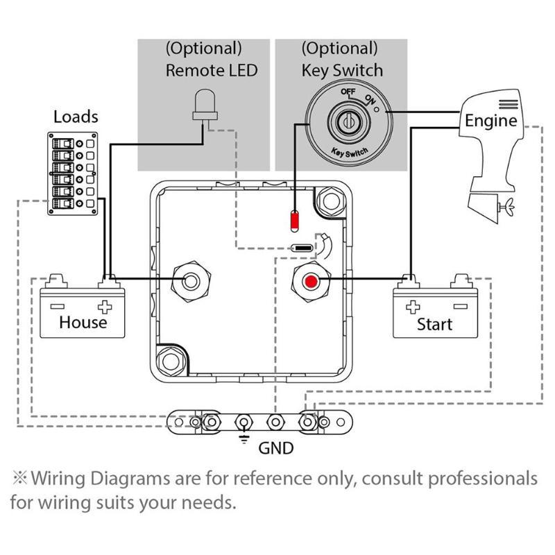
Bep marine battery switch wiring diagram. A wiring diagram is a kind of schematic which utilizes abstract pictorial signs to reveal all the affiliations of parts in a system. Two battery boat setup with wiring diagram. This dual battery setup for boats uses the blue sea add a battery kit for charging marine batteries. Collection of bep marine battery switch wiring diagram. Wiring diagrams include two things. Bat sw b1b2 selector 350a cont mc10 compare prev 1 next.
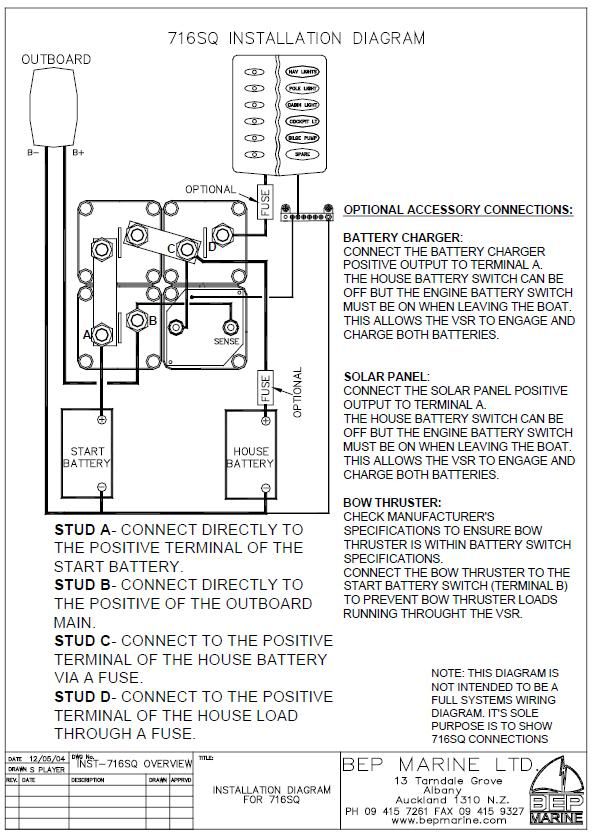
A wiring diagram is a simplified standard pictorial depiction of an electrical circuit. Boat part number is a new battery switch manufactured by bep marine part number b. Bep marine battery switch wiring diagram exactly whats wiring diagram. Symbols that represent the ingredients within the circuit and lines that represent the. It shows the components of the circuit because simplified contours and also the signal and power connections between those apparatus. Bep marine battery switch wiring diagram collection.
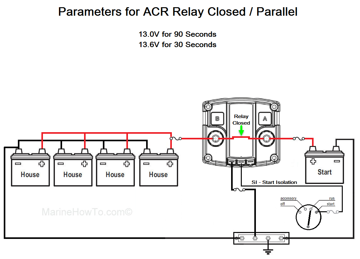
Posted on april 19 2018. A wiring diagram usually gives info about the family member position and arrangement of gadgets and also terminals on the gadgets to assist in structure or servicing the tool. Bep marine battery switch wiring diagram whats wiring diagram. Blue sea two battery switch acr dual charging system. This is a custom part and can be used on other boatsbep marinco battery switch cluster sur sbep battery switch ebay. It reveals the parts of the circuit as simplified forms as well as the power and also signal connections in between the tools.
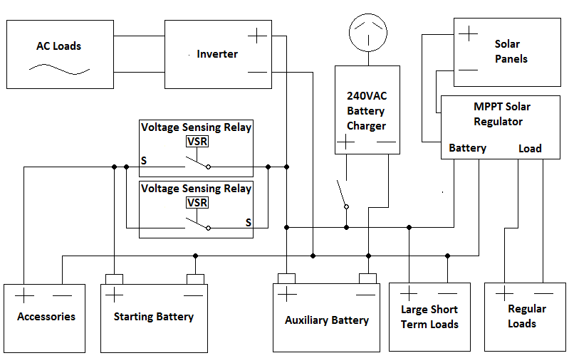
A wiring diagram is a kind of schematic which utilizes abstract pictorial signs to reveal all the affiliations of parts in a system. A bep marine vsr wiring diagram can be a compacted main stream picture representation of an electrical circuit. Symbols that stand for the components in the circuit as well as lines that stand for the connections in between them.
Gallery of Bep Marine Battery Switch Wiring Diagram