Failure to follow these instructions can result in equipment damage. Sales 1 800 463 9275.

Schneider Zelio Plc Trainer Design Stage 1 By Simon Cumming
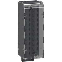
Bmx ami 0810 wiring diagram. It is suitable for use with the io modules with removable terminal block. This document presents one of the plantstruxure features using ethernet as the backbone around the modicon m580 offer and connecting an m580 local rack and m580 rio dropsthis guide provides detailed information about planning frequently used m580 architectures including the following ethernet io networks rio and distributed equipment integrated on the same physical network topology. Apply filters sort by. The bmxftw301 is a preformed cordset with 20 pin terminal block at one end and color coded wires at other end. 3 wires rtd channel 37. Product data sheet connections and schema wiring diagram vix pole input for channel x com x pole input for channel x iix current reading resistor input channel voltage sensor 0 channel 2 wire current sensor 1 4 bmxami0810.
3 bmx ami 0410 analog input module 51 4 bmx ami 0800 analog input module 71 5 bmx ami 0810 analog input module 93 6 bmx art 04140814 analog input modules 115 7 bmx amo 0210 analog output module 139 8 bmx amo 0410 analog output module 155 9 bmx amo 0802 analog output module 171 10 bmx amm 0600 analog inputoutput module 187. Abe 7cpa03 with bmx ami 0800 abe 7cpa03 avec bmx ami 0800 abe 7cpa03 mit bmx ami 0800 abe 7cpa03 con bmx ami 0800 abe 7cpa03 con bmx ami 0800 abe 7cpa03 与 bmx ami 0800 equipment damage do not apply negative current when bmx ami 0800 is associated with abe 7cpa03. Wiring diagram vix pole input for channel x com x pole input for channel x iix current reading resistor input channel 0 voltage sensor channel 1 2 wire current sensor. 35mm wide 15mm deep. 4 wires rtd msthermocouple input ms thermocouple input exrtd probe current generator output ex rtd probe current generator output nc not connected. Bmxami0810 isolated analog input module x80 8 inputs high speed.
Catalogue retriever servlet created date. 3 on am1 ed rail. 2 wires rtd channel 26. Wiring diagram 1 with removable terminal block cage screw or spring. Wiring diagram below example shows a probe configuration with. Post a question to one of our experts or start a discussion and get responses from supplier experts and fellow engineers in our community.
2 with fcn connector.
Gallery of Bmx Ami 0810 Wiring Diagram