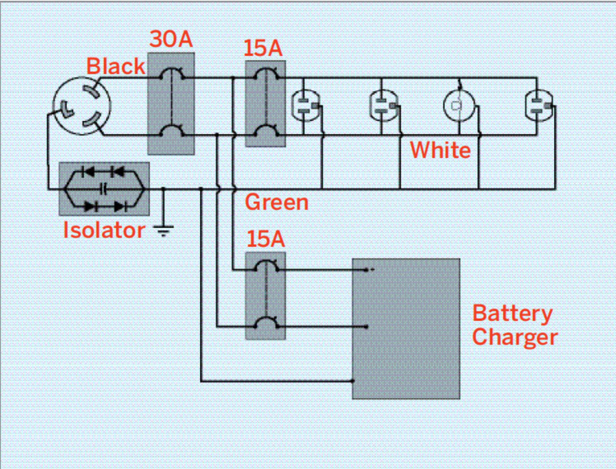
Minimum requirements for wiring diagrams. A wiring diagram is a streamlined conventional photographic representation of an electric circuit.
1956 Johnson 30hp Solenoid Help Page 1 Iboats Boating
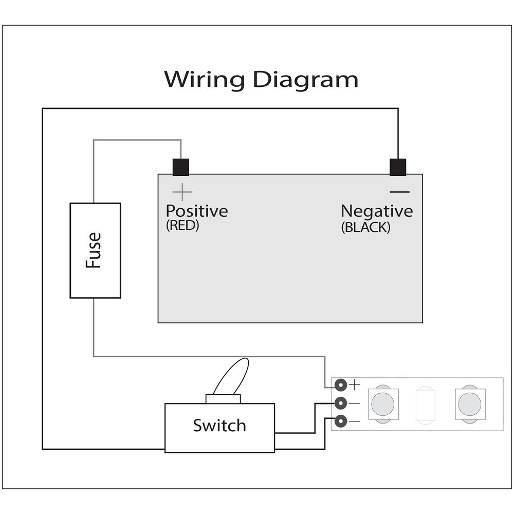
Boat dock wiring diagram. If you know just what to try to find it ll ended up being acquired behavior. Assortment of boat dock wiring diagram. Obtaining from point a to point b. The boats bilge pump float switch. Attached is a sample wiring diagram to be used as a guide. Boat dock wiring diagram what is a wiring diagram.
Boat dock wiring diagram. Boat dock wiring diagram a beginner s overview of circuit diagrams. Literally a circuit is the path that enables electrical power to flow. Buildings for private dwelling docks. Feeder from the main panel to sub panel shall be 4 wire for 240. It reveals the components of the circuit as streamlined forms and the power and signal links in between the tools.
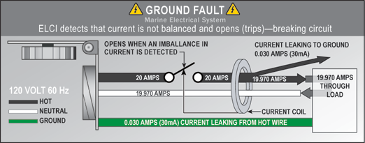
The objective is the very same. This way even if your battery switch is off if your boat starts filling with water the pump will still kick on. Contact your local fi re department for an inspection within seven days of supplying power to the dock. January 15 2019 by larry a. It shows how the electrical wires are interconnected and may also show where fixtures and components could be connected to the system. Location of ground fault interrupter all wiring on public property must be ground fault protected.
A first appearance at a circuit diagram may be complex yet if you could read a subway map you could read schematics. Its pretty standard in boat wiring to bypass the main battery switch for one thing. All wiring shall meet 2011 nec article 555 marinas and boat yards for all other docks. A wiring diagram is a simple visual representation from the physical connections and physical layout of your electrical system or circuit. The following represents the minimum information to be included on all wiring diagrams submitted for individual boat docks.
Gallery of Boat Dock Wiring Diagram