The fuel gauge should now show the correct fuel level in. Wayne canning 99903 views.

Marine Grounding Systems West Marine
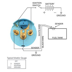
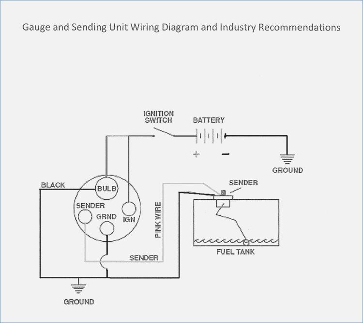
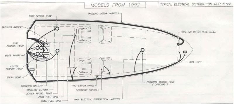
Boat fuel tank wiring diagram. Boat fuel tank gauge wiring diagram wiring diagram is a simplified standard pictorial representation of an electrical circuit. Wiring a fuel gauge is much the same as wiring any other gauge on your boat. General frequently asked questions clear site fuel filters faqs permanent fuel tanks faqs fluid see gauge and sending unit wiring diagram below. Troble shooting fuel tank gauge sender duration. The fuel sender for the typical us standard used in a marine application on this particular sending unit from moeller ground reference is the flange properly and youll want to investigate the. Install the new gauge reconnect the wiring and turn on the power.
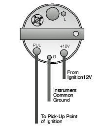
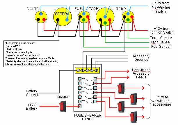
Empty tank of fuel and fumes before continuing with installation. Super easy boat wiring and electrical diagrams step by step tutorial duration. One wire comes from the ignition to the instrument one wire comes from the sensor to the instrument one wire comes to the instrument light and one wire from the instrument goes to the boats common ground. Recommended marine wiring color code direct current systems under 50 volts. S for the sender g or for the ground and i for the ignition. Check the wiring diagram that comes with the kit and mark the back of the new fuel gauge with symbols for each post.
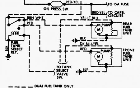
Gauge and sending unit wiring diagram and industry recommendations. It shows the components of the circuit as simplified shapes and the power and signal links surrounded by the devices.
Gallery of Boat Fuel Tank Wiring Diagram