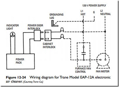
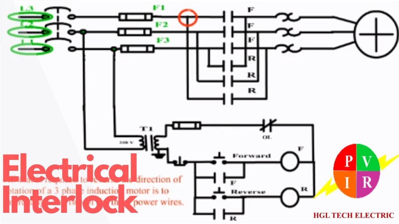
Wiring diagram since wiring connections and terminal markings are shown this type of diagram is helpful when wiring the. Interlock connection fixed adjustable fixed res heating element h adjustable by fixed taps res rheostat potentiometer or adjustable taps res diode or half wave rectifier.

Mobile Home Furnace Wiring Diagram Free Picture Free Picture
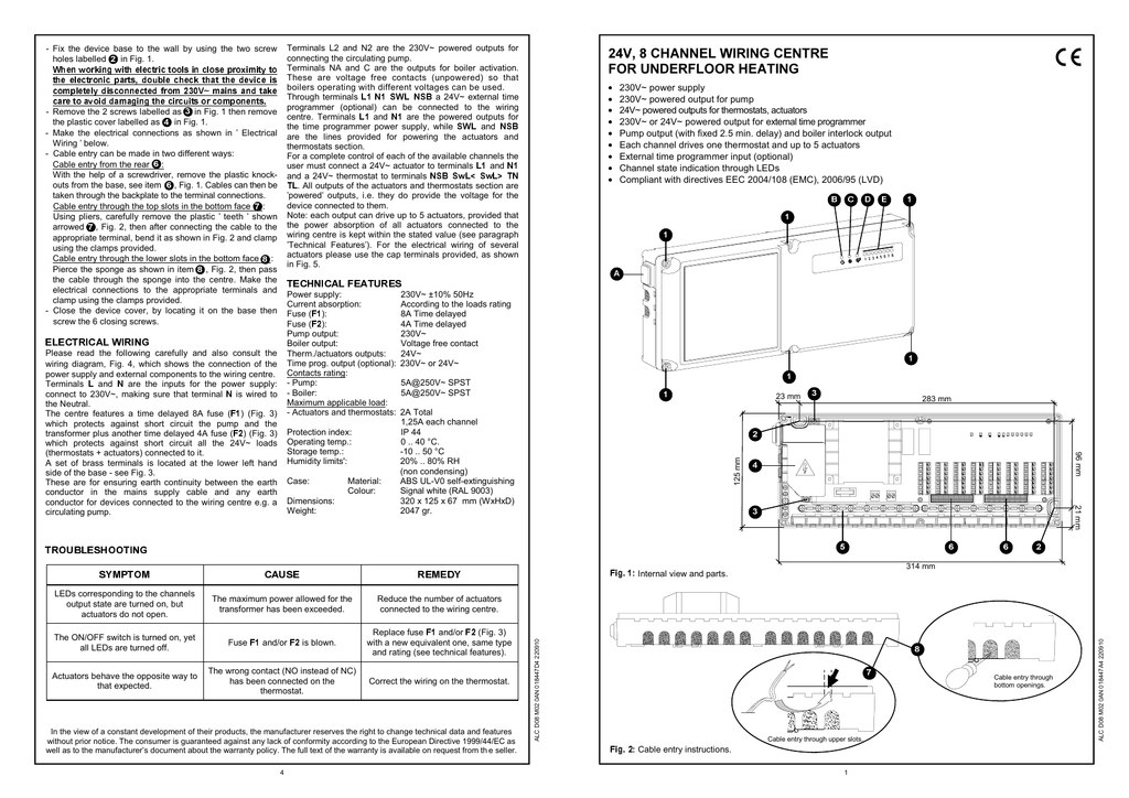
Boiler interlock wiring diagram. Ct 6 10 15 and 25 boiler wiring diagram. Ct 6 and 25 boiler wiring diagram. Most of the wiring diagrams are for natural gas powered steam boilers. Using the wiring diagram you supplied me. Instead it describes how the system has been wired in. 2installation description four wire two wire heating only two wire w furnace 24v terminal block thermostat terminals interlock relay w r r g g c y y 3 2 1 1 4 7 2 5 8 6 9 condensing unit 9 pin amp plug 120v.
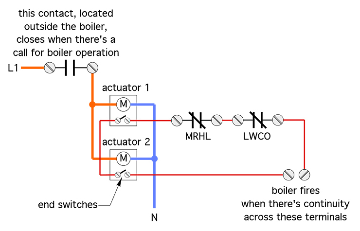
On the diagram no 8 direct to the boiler instead of the link through the tankstat. Assortment of ignition interlock wiring diagram. It reveals the elements of the circuit as streamlined forms and the power and also signal links between the gadgets. Boiler interlock isnt a physical control device. Wiring diagrams for oil burning and water boilers are noted. Ct 35 and 50 boiler wiring diagram.
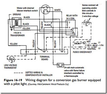
After turning off the electrical power to the furnace proceed to wire the thermostat and furnace according to figure 1. Controller 4ch to roomstat then boiler and pump feeds connected together to the return from the roomstat. Hrt 20 and 30 boiler wiring diagram. Its a wiring arrangement that prevents your boiler from heating your home when theres no need for it for example if the temperature that you set on the thermostat has been reached. A wiring diagram is a streamlined conventional pictorial representation of an electrical circuit. Here is a circuit diagram for a boiler interlock for a gravity system using tank and room thermostats.
Gallery of Boiler Interlock Wiring Diagram