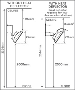
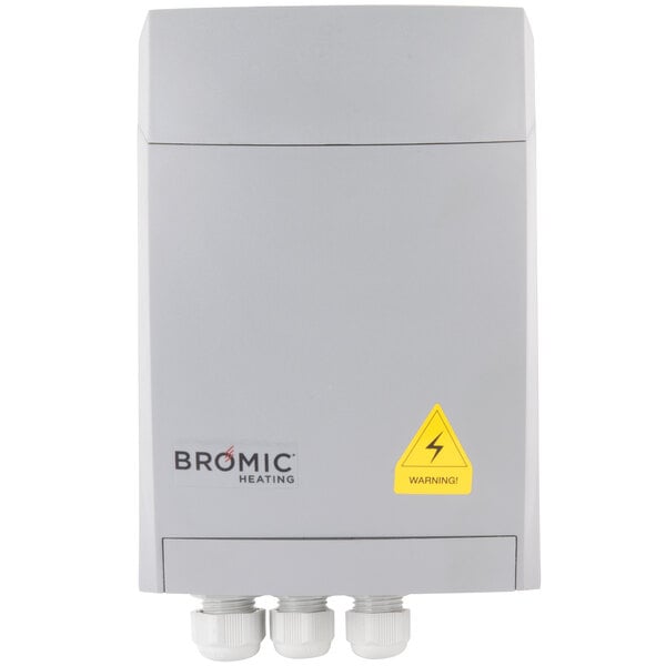
Bromic heater wiring diagram cvd1885 condensing unit control box bromic heater wiring diagram wiring diagram is a simplified satisfactory pictorial representation of an electrical circuit. Failure to do this may cause the heating element within the tube to sag and cause premature burnout.

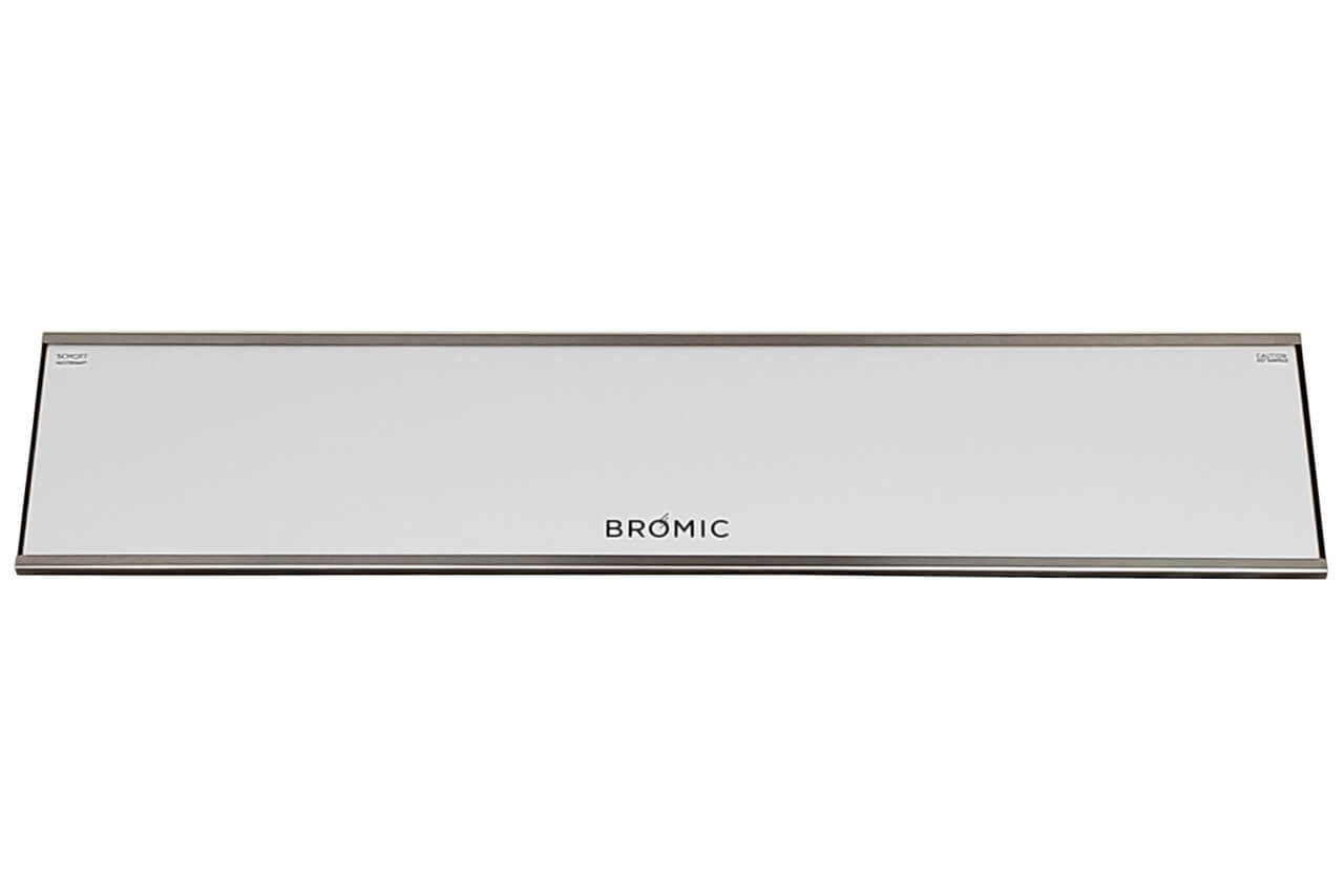
Bromic Bh0210004 25 43 Outdoor Heater Lpg Powered 500 Series
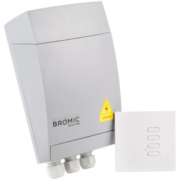
Bromic heater wiring diagram. A means for disconnection of the heater must be incorporated in the fixed wiring according to the local electrical codes. Program the wireless control as per operation. Program the wireless control as per operation section. 22 operation before programming select the output l1 or l2 using the switch as outlined in the wiring diagram. Tungsten 2000w 3000w 4000w and tungsten 6000w. Wire in power and heater as per the wiring diagram.
Wiring diagrams 14 servicing 15 maintenance 15 tube element replacement 15 replacement part list 16 troubleshooting 16 warranty 17. Study the wiring diagram at the end of this document before starting installation. Wiring diagram 4000w 6000w optional. Install heater so that the infrared elements are horizontal. If you would like any further information or assistance please contact the bromic support team. Power on the wireless control.
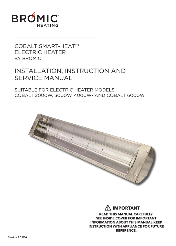
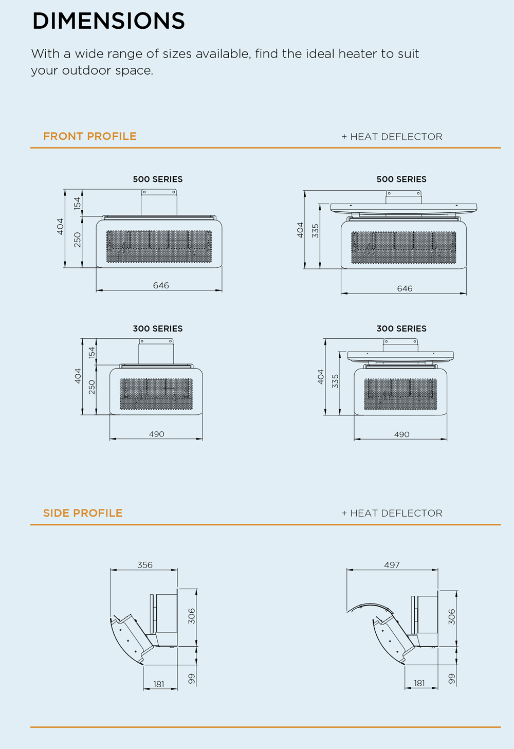
On this page you will find technical specifications and information on bromic heatings smart heat range of outdoor heaters. Use the dip switch function section for guideline. It shows the components of the circuit as simplified shapes and the aptitude and signal links with the devices. Power on the wireless control. Wire in power and heater as per the wiring diagram. Electric heater by bromic installation instruction and service manual suitable for electric heater models.
Setup the dip switch settings. Refit cover to the box. Do not mount the heater vertically. Open cover to the box.
Gallery of Bromic Heater Wiring Diagram