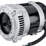
13 engines generators 1. The rotor shaft connects to the alternator.
Generator Excitation Control Systems Amp Methods Shunt Ebs
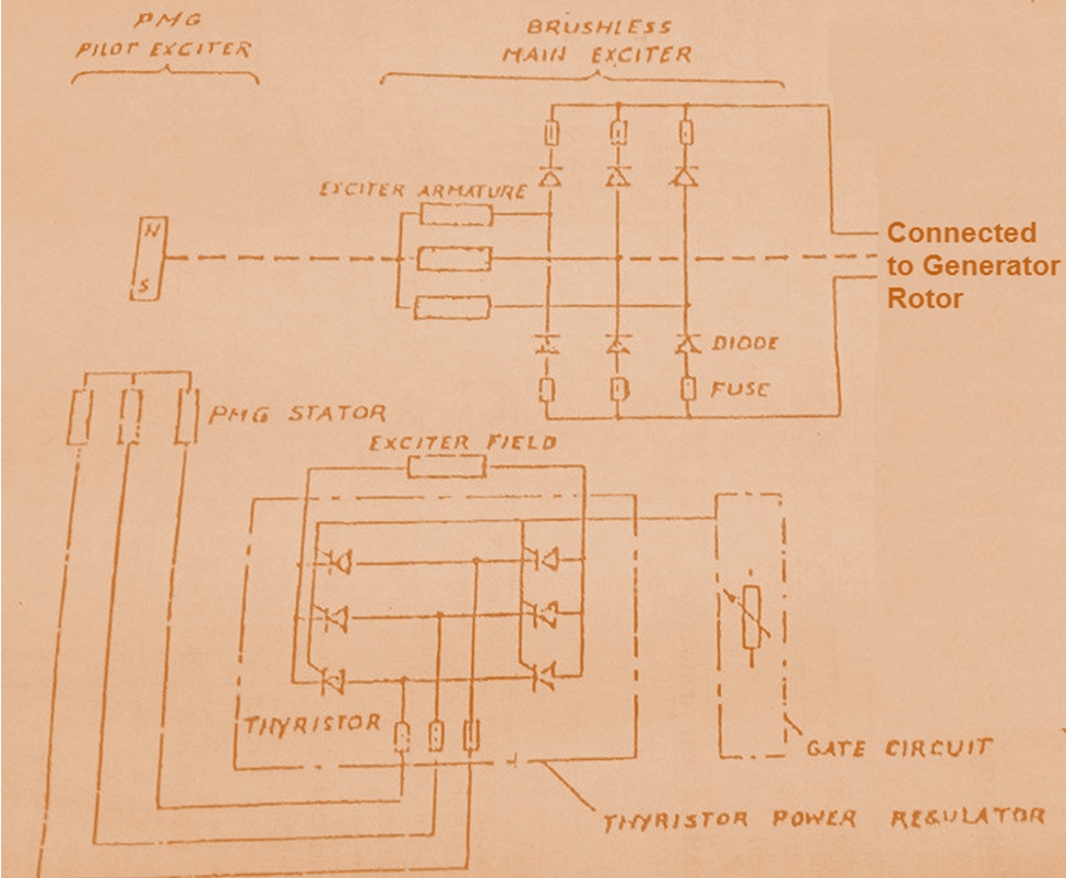
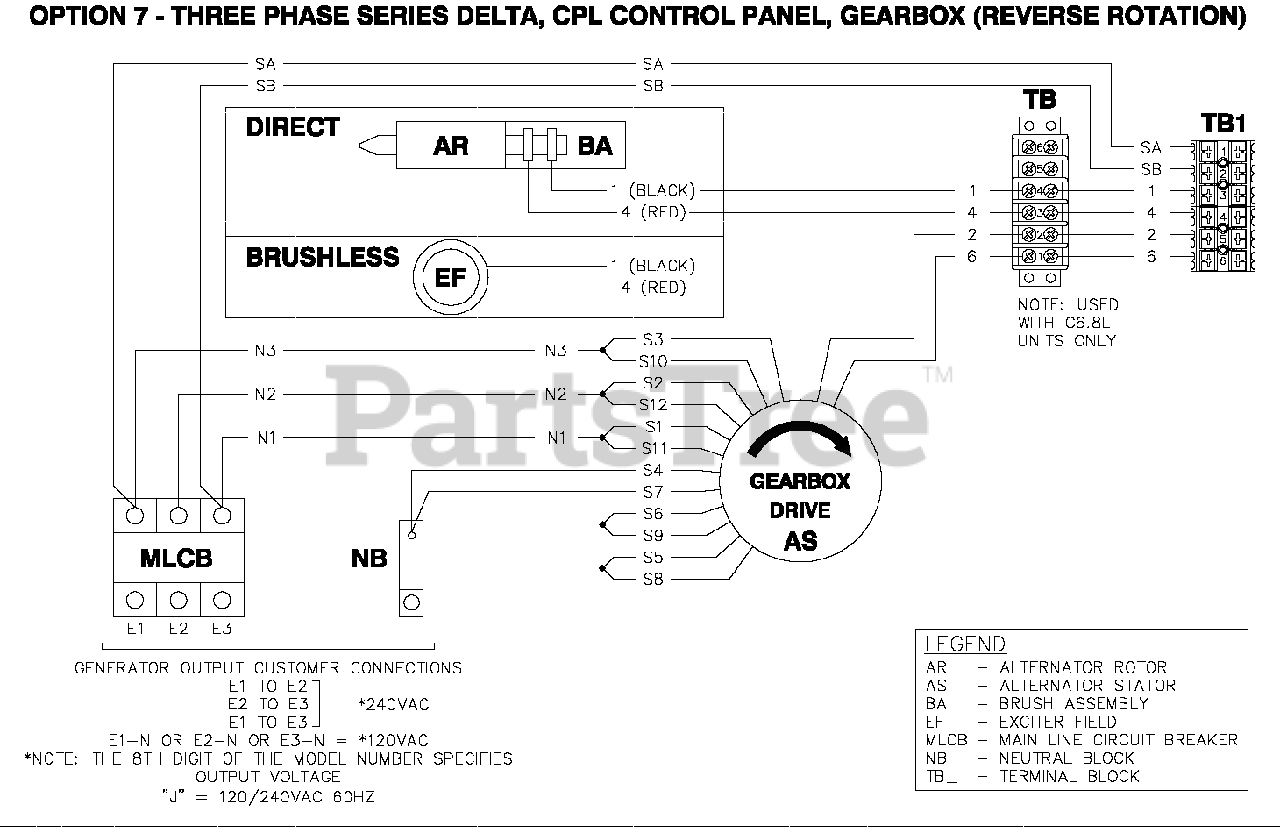
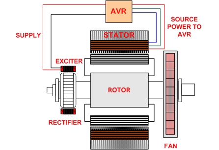
Brushless generator wiring diagram. The larger one produces power as described above. Pay particular attention to making sure that the wires connected to the generator output are of a heavy enough wire gauge to carry the output current rated output current. Brushless generator schematic to energize the field dc excitation must be applied to the generator field coils. Be generator electrical testing. When two cables in a brushless generator make a connection and intersect one point is automatically added to the joint but in case two wires cross without any form of communication then no point is added and therefore lines will move forward. Rectifiers hold the rotor shaft on to the alternator.
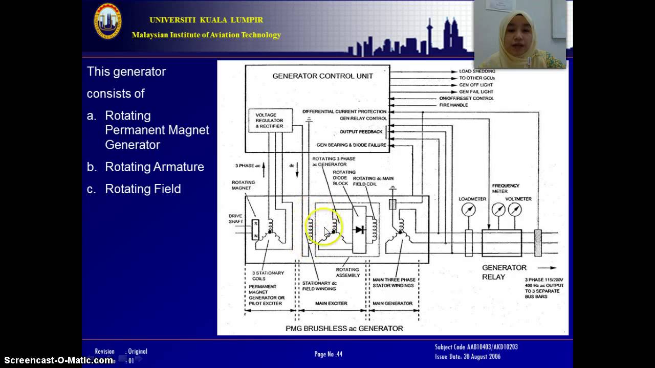
Operation principle of brushless alternator in all alternators voltage may be generated by rotating a coil wire in the magnetic field or by rotating a magnetic field within a stationary coil wire it doesnt matter whether the coil is moving or the magnetic field is moving. The bc generator is a brushless self excited generator which requires only the driving force of the engine to produce an ac output. Wiring diagram 46876. The alternator acts as the dc power source for the main rotor. Army tm 9 6115 644 24 air force to 35c2 3 446 12 marine corps tm 09249a09246a 242 generator stator exciter figure 4 10. It produces a dc voltage which is fed directly to the field coils of the main alternator.
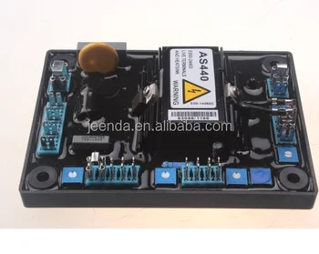
I do see a small capacitor on it and if you unplug it nothing comes out. I contacted harbor freight and they are worthless when it come to a remedy of thing to check. It has stationary field coils and a rotating armature with a rectifier. Output voltage and frequency as shown in the wiring diagram below. Brushless generators a brushless system actually contains two alternators on one shaft. I think it is a brushless type.
The stator houses two sets of windings. Connect output wiring to the output terminals u1 and u2 inside the terminal box of the generator. Reason being the wiring diagram is an as wired diagram and not a schematic so. Understandable it is not suppose to be a 240 generator. The excitation current is supplied from a brushless exciter mounted on the generator shaft. A brushless generators main parts include stator coils stator plates armatures rotator shaft rectifiers and an alternator.
The smaller one is the exciter.
Gallery of Brushless Generator Wiring Diagram