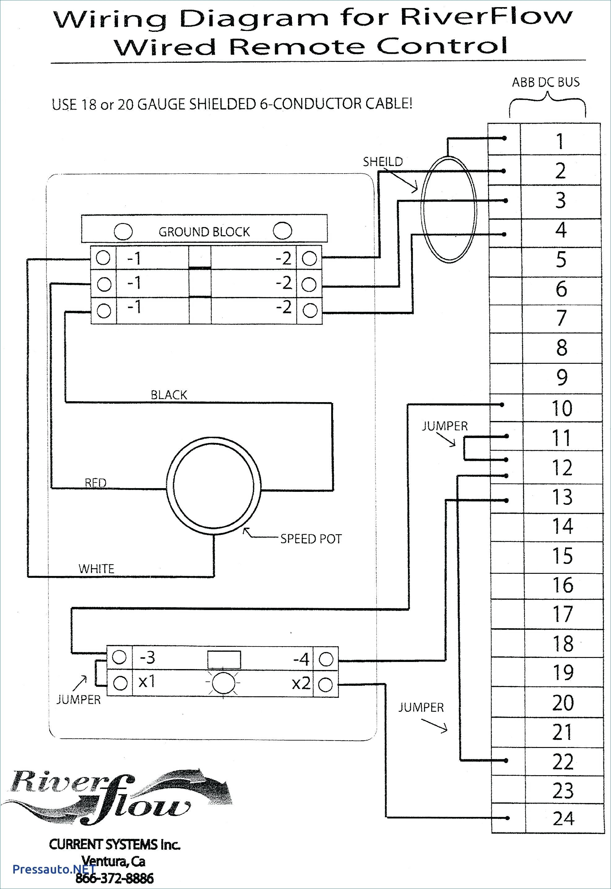
The yellow yelblk violet brown red and white converter connector wires are all class 2. The 2w its mounts through a ½ hole which may need to be made in the luminaire or could come pre punched by the luminaire supplier.

1999 Suzuki Sv650 Wiring Diagram Auto Electrical Wiring Diagram
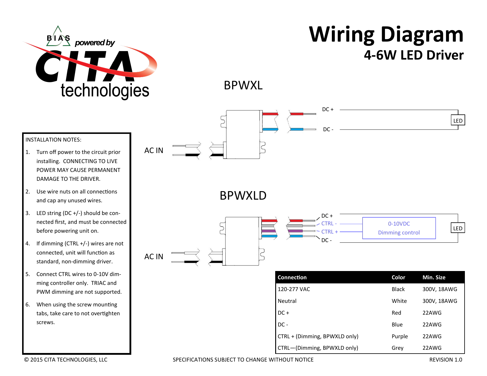
Bsl310 wiring diagram. 1534 x 225 x 118 369 mm x 58 mm x 30 mm. See the wiring diagrams for details. Make sure the necessary branch circuit wiring is available. 2 wire input reduces wiring errors compatible with a variety of led strip manufacturers compatible with ac drivers and led loads rated for class 2 selectable output rohs compliant 140 225 118 145 dimensions 145 x 225 x 118 mounting center 140 led bsl310. Bodine bsl310 emergency led driver 120277v up to 10 watt led emergency driver input voltage. To prevent high voltage from being present on yellow yellow.
The emergency driver must be fed from the same branch circuit as the ac driver. An unswitched source of power is required. Consult the factory for other wiring diagrams. Listed to ul924 and tested to csa 222 no. Ul recognized factory installation indoor and damp output class 2 compliant bsl310 is field installable when used with the philips evokit led retrofit luminaire and installed by licensed. Operates an led load of up to 10w at nominal battery voltage for a minimum of 90 minutes.
For short term testing of the emergency function the battery must be charged for at least one hour. Bsl310 is field installable when used with the philips evokit g2 led retrofit luminaire. Wiring diagrams 2 warning. 2 wire illuminated test switch. May be used with other drivers. Bsl310 emergency led driver.
Wiring diagram electrical wires cable schematic philips bsl310 emergency ballast by philips bodine 13522d6 bodine b50st emergency ballast wiring diagram library emergency led drivers w universal lighting technologies. High temperature maintenance free nickel cadmium battery 7 to 10 year life expectancy. Philips bodine bsl310 wiring diagram. Option b contains the illuminated test switch wiring in its own conduit with the test switch and a wall plate included in a separate parts kit. By admin october 12 2018. Option a the illuminated test switch is located in one conduit and product wiring in the other.
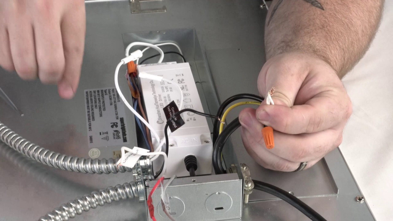
Bsl310 102918 ni cd class 2 output. Temperature rating ambient 0c to 55c 32f to 131f dimensions. Ul listed for us and canada. Wiring diagrams 4 note 1. 141 for field or factory installation indoor and damp. Mount the supplied 2w its 2 wire illuminated test switch in a location that is visible and accessible by maintenance personnel.
Bsl310 091013 ni cd universal input class 2 output. Emergency driver for linear led strips class 2 output 10 watts output power. Wire the test switch per wiring diagrams provided on these instructions. The emergency driver must be charged for at least 24 hours before conducting a long term test. Emergency driver and ac driver must be fed from the same branch circuit typical schematics only.
Gallery of Bsl310 Wiring Diagram