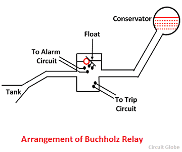
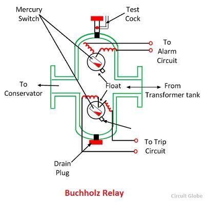
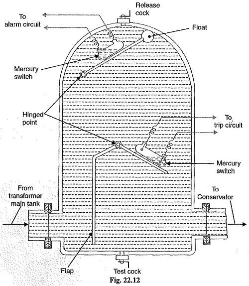
An upper side mercury switch is connected to an alarm circuit which used to give an alarm during an incipient fault in the transformer tank. It is a mechanical device that accompanies two numbers of mercury electric switches for sending the electrical command to the relays.

Buchholz Relay Of Transformer And Working Of Buchholz Relay
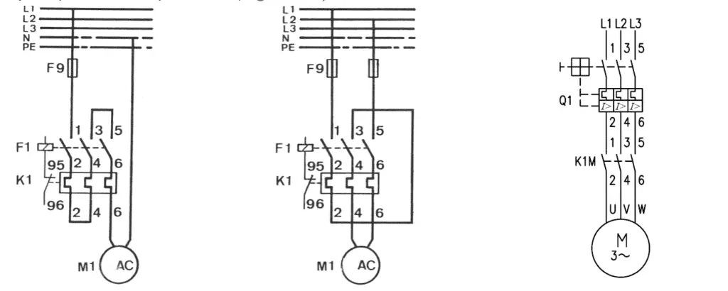
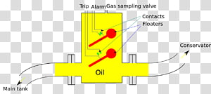
Buchholz relay wiring diagram. Wiring diagram of buchholz relay. Short circuit faults such as inter turn faults incipient winding faults and core faults may occur due to the impulse breakdown of the ins. Buchholz relay working diagram buchholz relay consists of two hinged floats one at the upper side and another one at the bottom side in the chamber. Buchholz relay standard wiring diagram mounting sketch. Type a 2 no contacts 1 for alarm. It can only be used with oil immersed transformers equipped.
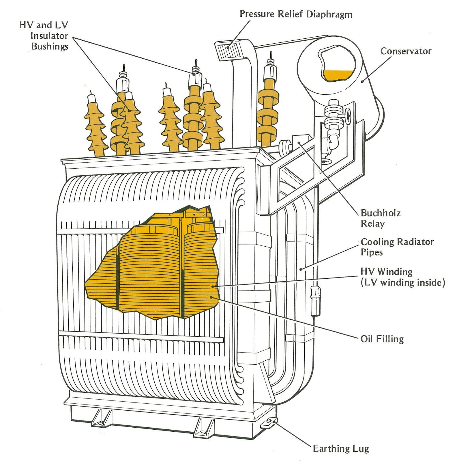
Buchholz relay diagram working principle. Buchholz relay mounting sketch. 1 for trip signalling for oil loss and oil surge. The transformer is filled with hydrocarbon oil for the insulation of winding and cooling of the transformer. Actuated buchholz relay as this device is the only means of detecting incipient faults which if unnoticed can cause heavy failures. 2it detects the incipient faults at a stage much earlier than is possible withother forms of protection.
Buchholz relay is used for the protection of transformers from the faults occurring inside the transformer. Wiring diagrams 51 standard wiring diagrams standard wiring diagram available are. By mari marina on june 21 2020 in wiring diagram 189 views. If an internal fault occurs of the transformer the. It is the simplest form of transformer protection.
Gallery of Buchholz Relay Wiring Diagram