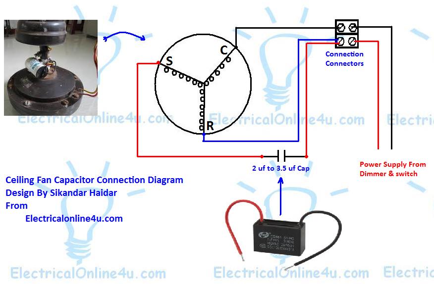
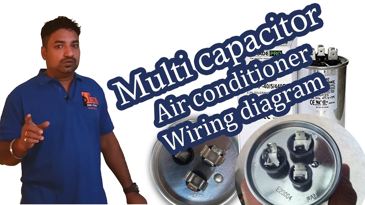
Round dual capacitors on the top should be marked. Click here to view a capacitor start motor circuit diagram for starting a single phase motor.

Power Acoustik Capacitor Wire Diagram Hondadr Dodge
Capacitor wiring diagram. Usually the wiring diagram is glued to one of the panels on the air conditioner. Often a stamp on the side of the relay shows the wiring diagram. It includes instructions and diagrams for various types of wiring methods and other items like lights home windows etc. How to wire a run capacitor to a motor blowers condensers sometimes when a blower or condenser fan motor goes bad a technician or even a diyer has issues wiring the new motor and capacitormost motors come with clear instructions or a wiring diagram on the side. Herm com and fan. Each component ought to be placed and linked to different parts in particular manner.
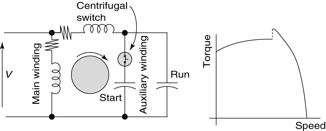
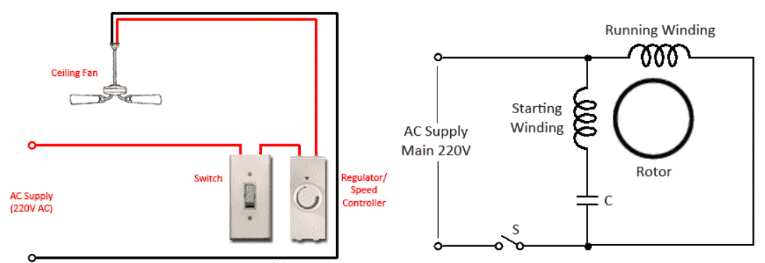
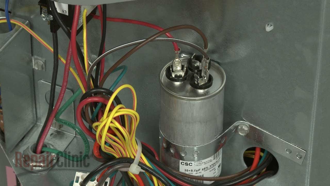
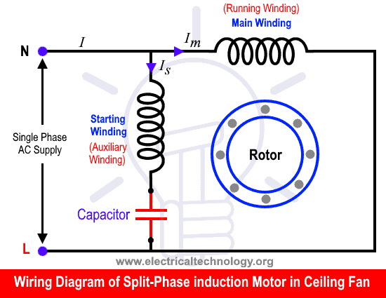
Single phase motor wiring diagram with capacitor baldor single phase motor wiring diagram with capacitor single phase fan motor wiring diagram with capacitor single phase motor connection diagram with capacitor every electrical arrangement is made up of various unique pieces. Also read about the speed torque characteristics of these motors along with its different types. The diagram identifies the capacitor and relays wire color and the wires function. You should see a wiring diagram glued to the inside of the air handler cabinet or to the inside of the blower compartment door. However some people still struggle with the wiring part of the motor to the capacitor. Look at the wiring diagram for your specific hvac equipment and find the capacitor where youll see its wires and their identities.
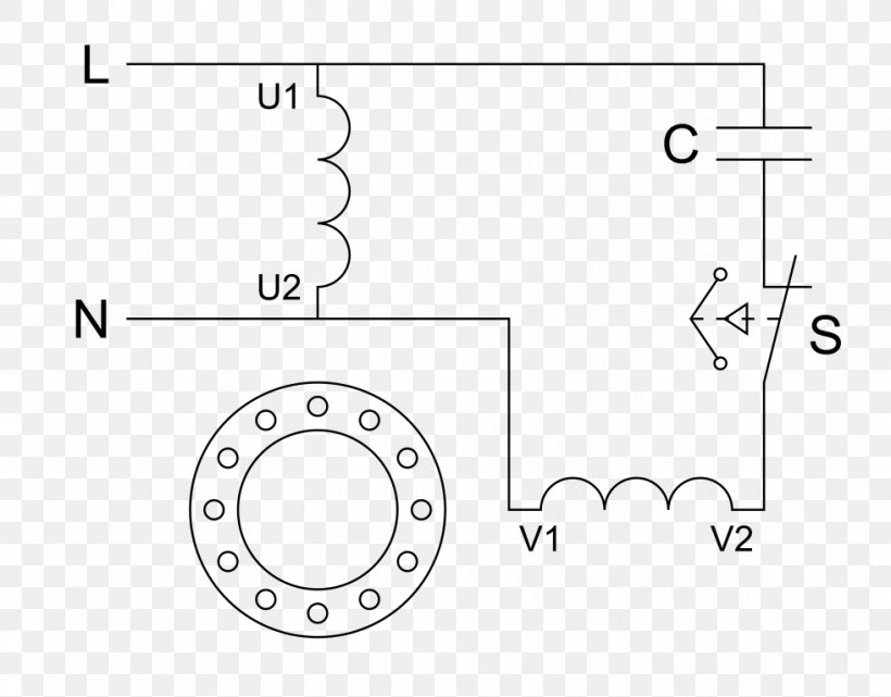
The wiring diagram identifies the fan motor and compressors wire colors and functions. Inspect the start capacitors wiring diagram. Learn how a capacitor start induction run motor is capable of producing twice as much torque of a split phase motor. Wondering how a capacitor can be used to start a single phase motor. How to connect single phase single phase motor wiring diagram with capacitor wiring diagram consists of many in depth illustrations that show the link of varied things. Hope you can read it.
A wiring chart on the fan motors case also identifies the fan motors wire colors and each wires function. Variety of baldor motor capacitor wiring diagram. The letters stamped into the compressors housing near the wire terminals identify each terminal function. Step 3 push the wire terminal on the start capacitor relays common wire usually the black wire to the common terminal on the load side of the. A wiring diagram is a simplified traditional photographic depiction of an electrical circuit. It reveals the parts of the circuit as streamlined forms and also the power and also signal connections between the tools.
You would need to look at the wiring diagram that came with the unit.
Gallery of Capacitor Wiring Diagram