The master switch does not turn on the power directly. Cessna split master switch diagram.
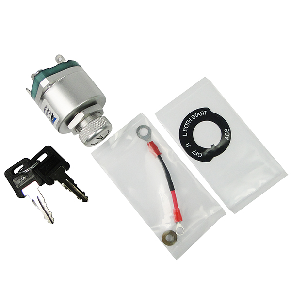
Cessna Split Master Switch
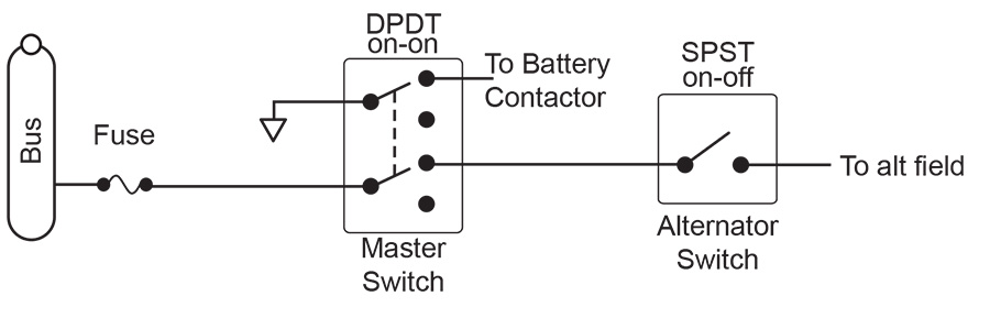
Cessna split master switch wiring diagram. This manual may be found in the applicable model wiring diagram. 3401 hwy 21 w hangar 500 faribault mn 55021 airport identifier. Left rocker normally used for alternator and right half for battery. The field wire should only be removed from the alternator with the master switch off. Cessna propeller aircraft customer care supplies and publications. Aircraft wiring usually consists of tin coated copper stranded wire covered by insulation.
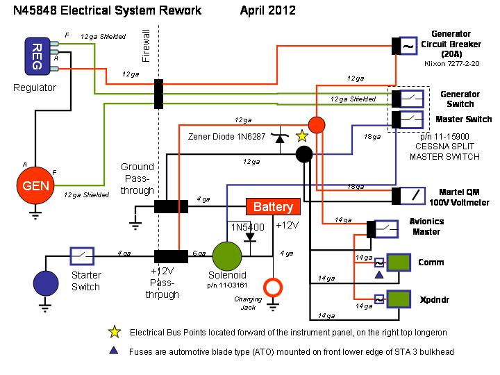
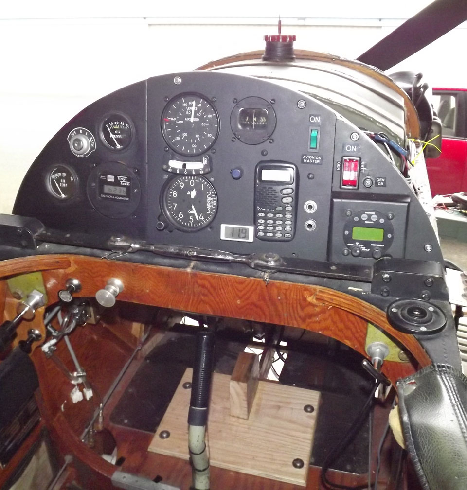
The voltage regulator can be ruined if that happens. The positive and negative terminals on the switch are reversible you may wire them in either direction. When you operate the master switch it grounds the other end of the coil to operate. The left side of the master switch provides 5 amp power to energize the alternator. Im looking at the undocumented installation of an avionics master switch. This is a wiring manual on cd for the cessna st aircraft.
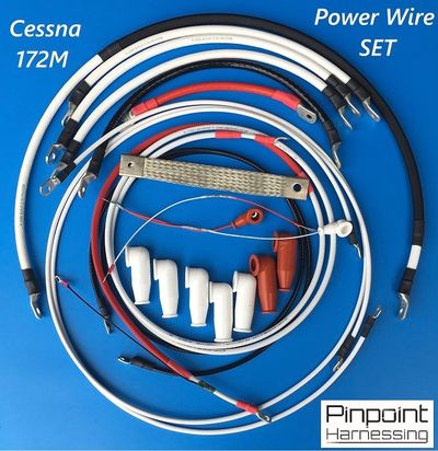
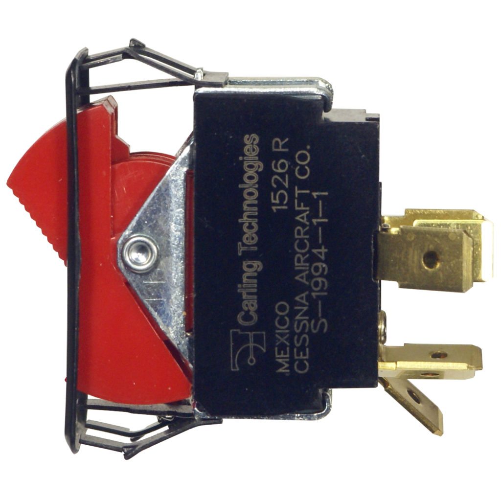
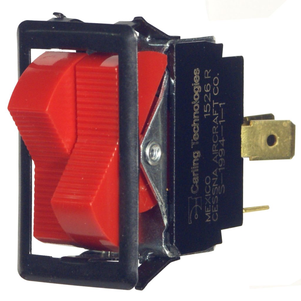
It operates a solenoid which connects the battery positive cable to the starter and from there to the fuses. The coil in the solenoid is connected to the battery positive cable post with a short jumper wire. Purchased a cessna style mastersplit switch from ac spruce in order to eliminate toggle type switches for isolating the battery in the event of an alternator failure. This versatile split beige master switch has been used in virtually all single engine cessna models since 1970 and can be used in most light aircraft with single alternator systems. Edges of pages a little dirty the insides are. The switch is split to separate the two systems.
Its a simple 35a current protected spst switch in series with smaller breakers that power to all the com nav gps and xpdr gear on the airplane. If the master switch is turned on with the wire removed take precautions to prevent the field wire from touching anything that would allow it to short to ground. The cessna split master part number 11 15900 does not include any specific wiring instructions. Problem is that it did not come with any wiring diagram or have any of the tabs on the back of the swich marked. 22 25 08 in. Great people great products great service.
The cessna maintenance manual supplies all information needed for this installation. Wire gauges may vary depending on your electrical loads. Until the early 90s wire was insulated with pvc but it has since been phased out and replaced with tefzel. It does happen to be a 35a switchbreaker installed at the load end of a 12 awg wire from the power bus.
Gallery of Cessna Split Master Switch Wiring Diagram