Rcdmcb 1pn 1m 20a 45ka 30ma slim. Clipsal rc and 4rc series residual current device wiring diagrams 1 2 main switch single phase e 3n 4n clipsal rcbm 4rcbm and 4rcbe series combined mcbrcd wiring diagram a warning combined max.

Schneider Mcb Wiring Diagram Diagram Base Website Wiring
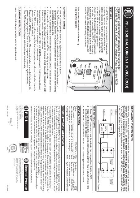
Clipsal rcd mcb wiring diagram. Rcd as it does not provide protection against overload. If the rcd unit incorporates an optional alarm then it can be muted by pressing the press to mute button. Rcd and mcbs slim in size big on features 23041. 13 mb pdf clipsal timers wont forget. View the rcbe22030s product features specifications documents and related faqs. How to wire rcd residual current device.
Clipsal resi max circuit protection the complete residential solution 124301. The press to mute visual indicator will remain on until the rcdmcb has been reset. View the rcbe21630s product features specifications documents and related faqs. Your rcd includes double pole switching to give added safety against faulty wiring. View the rcbm21630 product features specifications documents and related faqs. Residential smart wiring security and safety.
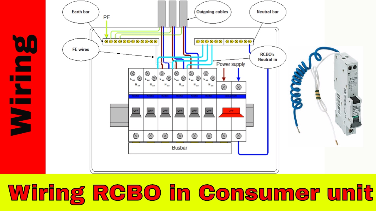
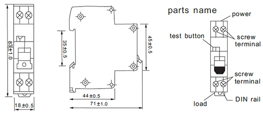
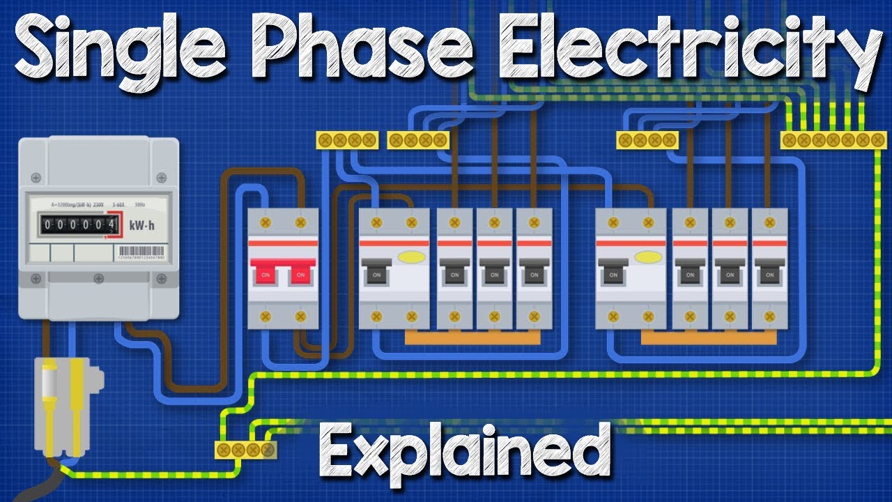
Demand of these three circuits must not exceed rating of rcd ol n n n a neutral link do not earth ol clipsal rcd 2 4n 1 3n a mains switch a e n n an. In this single phase home supply wiring diagram the main supply single phase live red wire and neutral black wire comes from the secondary of the transformer 3 phase 4 wire star system to the single phase energy meter note that single phase supply is 230v ac and 120v ac in usthese two lines line and neutral from energy meter are. A mechanical indicator on the front of the rcdmcb highlights whether the fault is an rcd or mcb fault. Residential smart wiring security and safety. Combination rcdmcb 2 module 2 pole 16a 30ma 6ka c curve. Rcdmcb1pn 1m 16a 45ka 30ma slim.
A n ol ol ol v. Clipsal rcbm 4rcbm and 4rcbe series combined mcbrcd wiring diagram nn a ol n main neutral link a n to unprotected circuits n a v v v v to rcd protected circuit note. For balanced 2 and 3 circuits no neutral is required a a e n mains switch main neutral link clipsal rcd 3 n 1 5 2 n 4 6 a to rcd protected circuits n a n to hws. Prior to wiring ensure the supply is disconnected at the distribution board and study the connection diagram before terminating any wires. Electrical contractors or building companies are not bound to follow these prices and may charge more or less than the values listed. 4tc and 4tcd1 switchboard mounted programmable timers 26250.
Gallery of Clipsal Rcd Mcb Wiring Diagram
.jpg)