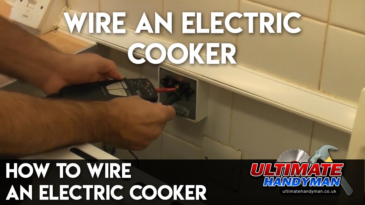
The product standard for cooker control units is bs 41771992 specification for cooker control units. A video showing process of wiring cooker to a cooker connection unit.
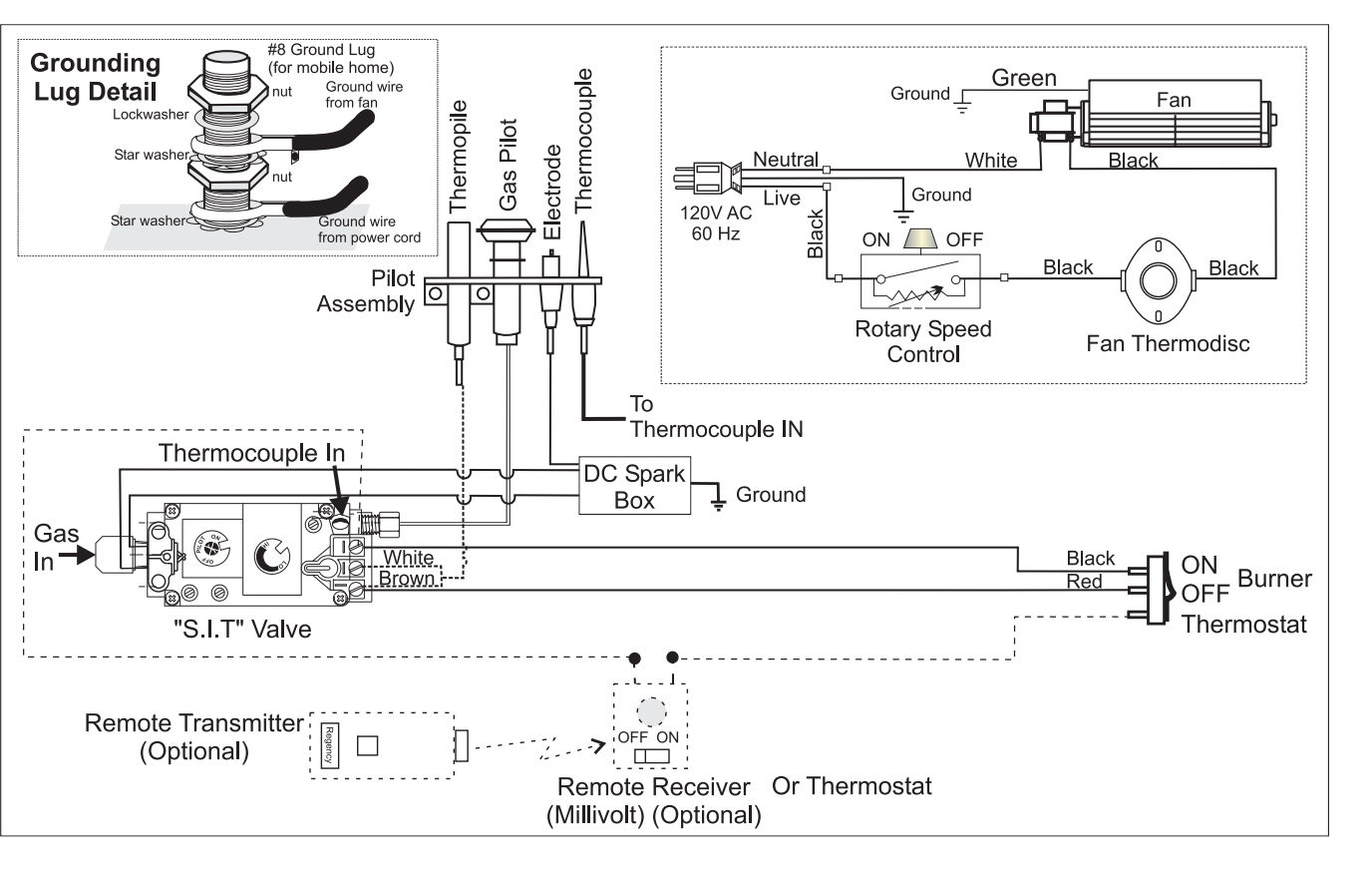
Gas Cooktop Igniter Spark Module Diagnosis Amp Repair How To
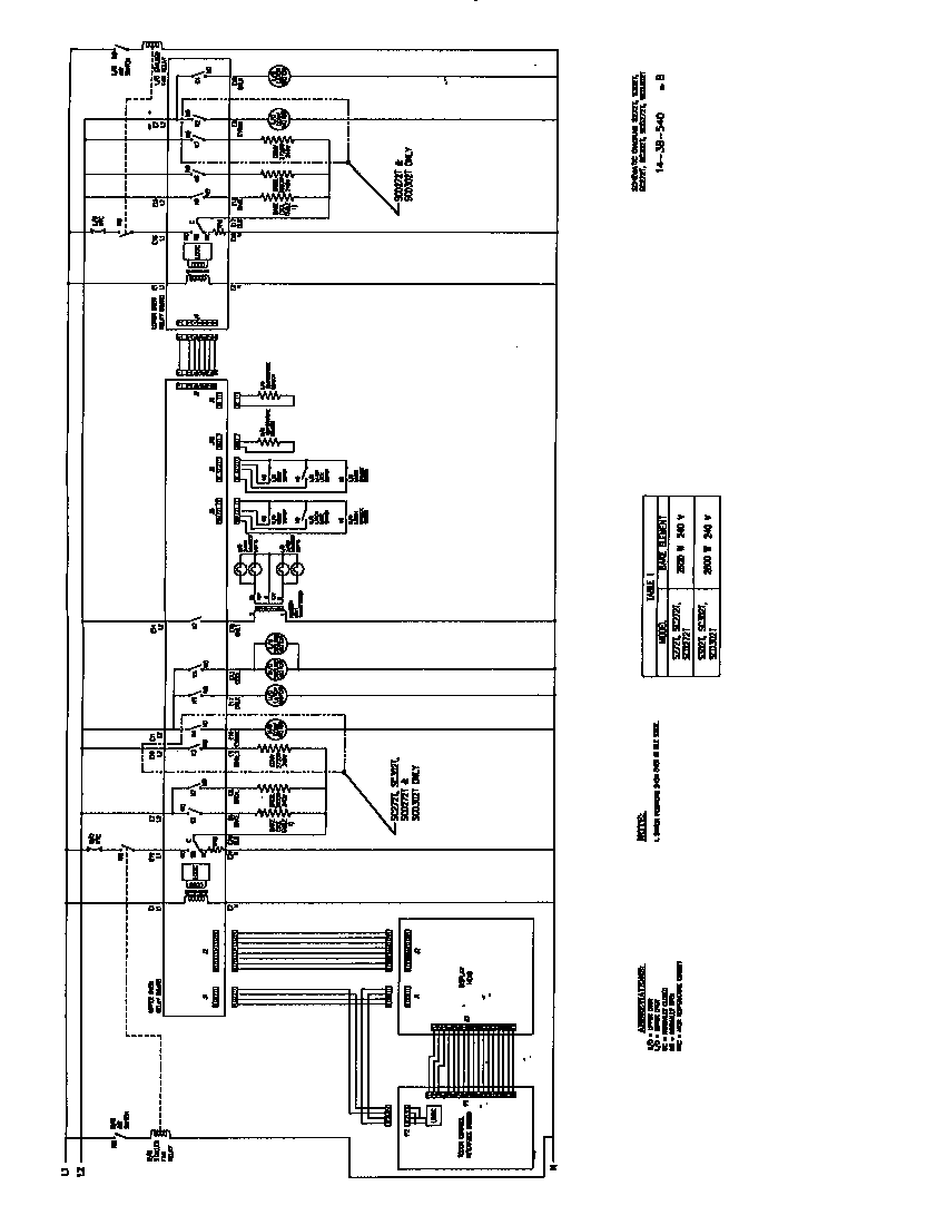
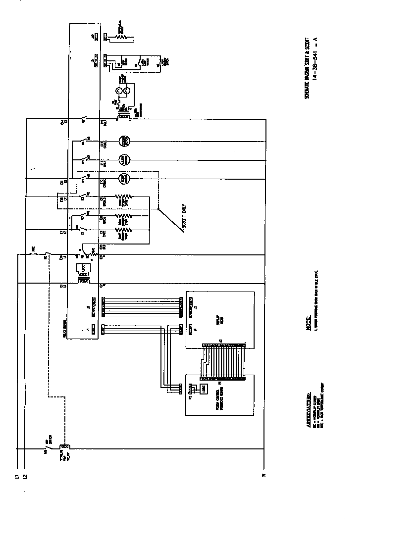
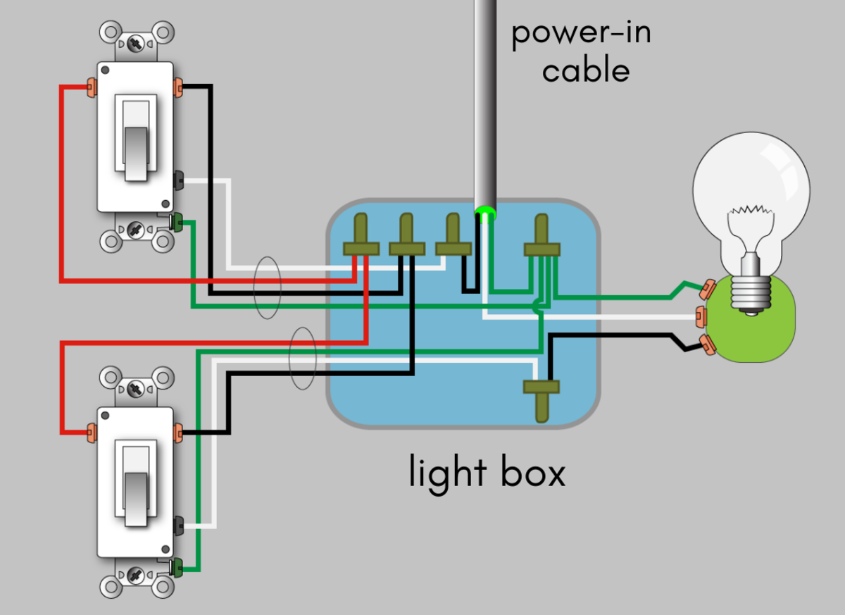
Cooker control unit wiring diagram. Draw a free body diagram. Ford tractor parts diagram. A cooker switchcontrol unit may be used to control two or more cooking appliances in the same room such as an ovengrill and a separate hob unit as permitted by regulation 476 03 04 provided it has sufficient current rating. Join the wires to the wall mounted control units terminals. This should make it far easier to wire the new product. Cooker control unit wiring diagram.
The cooker control unit fits into a standard patress box just like a socket outlet or switch and may be flush or surface mounted. Cooker control unit wiring diagram wiring diagram is a simplified customary pictorial representation of an electrical circuit. Cooker control unit the switch controlling the supply to the cooker has a rated current of either 32 a or 45 a and the switched socket outlet has a rated current of either 13 a bs 1363 type or 15 a bs 546 type. This video is unavailable. Wiring diagram illustrates how the components are connected. Pioneer avh x2600bt wiring harness diagram.
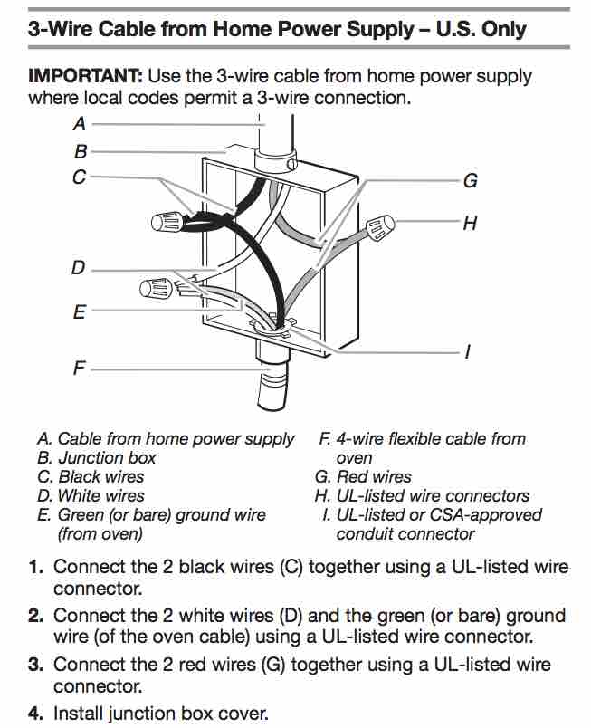
Wiring cooker switch how to connect install cooker. How to wire oven hob diversity on a cooker circuit wiring diagram duration. Some cooker control units offer simple switching facilities but others include a standard socket. Before commencing with the installation ensure the back box is firmly fixed to the wallceiling. Uml network diagram examples. A wiring diagram is a comprehensive schematic that depicts the electrical circuit system shows all the connectors wiring signal connections buses terminal boards between electrical or electronic components and devices of the circuit.
It shows the components of the circuit as simplified shapes and the talent and signal connections amid the devices. Basically match the cookers wire colors to the ones in the control unit. Socket outlet of a cooker control unit if one is fitted. If replacing an existing switch or cooker unit always take careful note of the cables and any terminal markings there may be before removing the old unit. A video showing how to connect install cooker control switch unit. To insert them rest the insulated part of each wire flat against the unit then push the exposed ends into the open slots.
Look inside the control unit to see approximately 3 wires of different colors. Cooker control switch featuring a 13amp standard plug socket. October 12 2018 october 11 2018 florine 0 comments. Positioning the switch or control unit should be readily. 51 surround sound circuit diagram.
Gallery of Cooker Control Unit Wiring Diagram