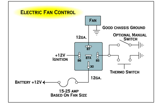
To switch a relay on the two smaller wires make the connection from hot to ground. A relay kit our part number ccfkrl will include everything you need to properly wire up your electric cooling fans with the exception of additional wiring needed to complete all of the circuits.
How To Properly Wire Electric Cooling Fans
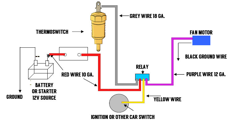
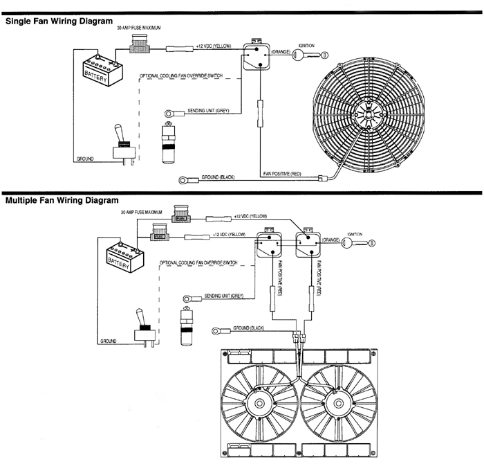
Cooling fan relay wiring diagram. Suggested electric fan wiring diagrams suggested primary cooling fan single speed onoff using 12 volt switching devices only for primary activation note. Now take the power wire from your fan and connect it to the wire that is going through the firewall. Get the 10 gauge wire and place it through the hole in your fire wall. Cooling fans are now controlled by the ecm through the respective module network and using duty cycle control signals. Next splice together both black wires. Relays shown in these diagrams can provide options.
When installing an auxiliary fan or simply wiring the factory fan so that the driver can manually turn the fan on and off make sure the fan is turning in the right direction. Start with taking both of the positive wires from the fans and run it to the yellow wires on each relay. The first part of the installation is to install the electric fan to your radiator and remove the mechanical fan. This will be the wire that connects your switch to your fan power wire. Here youll also be exposed to the current path voltage and sensor signal. Variety of hvac fan relay wiring diagram.
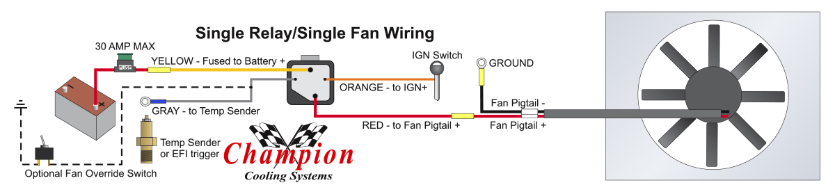
We include instructions for a single fan and a dual fan using one or two relays in every relay kit we sell. It uses a 40 amp electric relay and electric fan sensor. How to wire a relay for a radiator fan by don bowman. So now we have a wire that goes through the engine bay to the cabin of your car. Hayden flex a lite or perma cool brands can provide a 12 volt output when activated. Or a single relay could be used to control both fans.
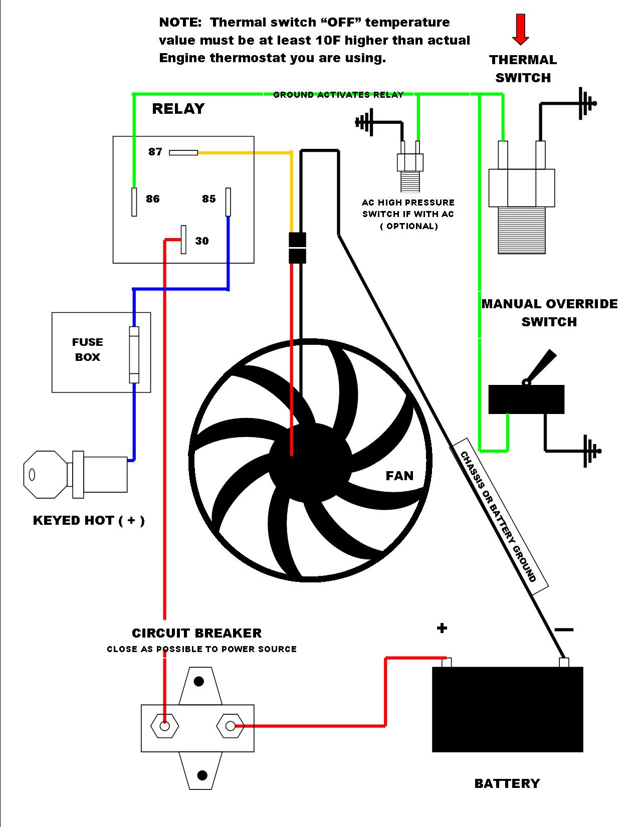
You will then need switched power usually from your ignition switch wired to the blue wires on the relays. A wiring diagram is a simplified standard photographic depiction of an electrical circuit. If the fan is not turning in the right direction air will be blown away from the radiator and will not help to. Most stand alone adjustable thermostats ie. It reveals the parts of the circuit as streamlined shapes and the power as well as signal connections between the devices. Testing low and high speed cooling fan relays.
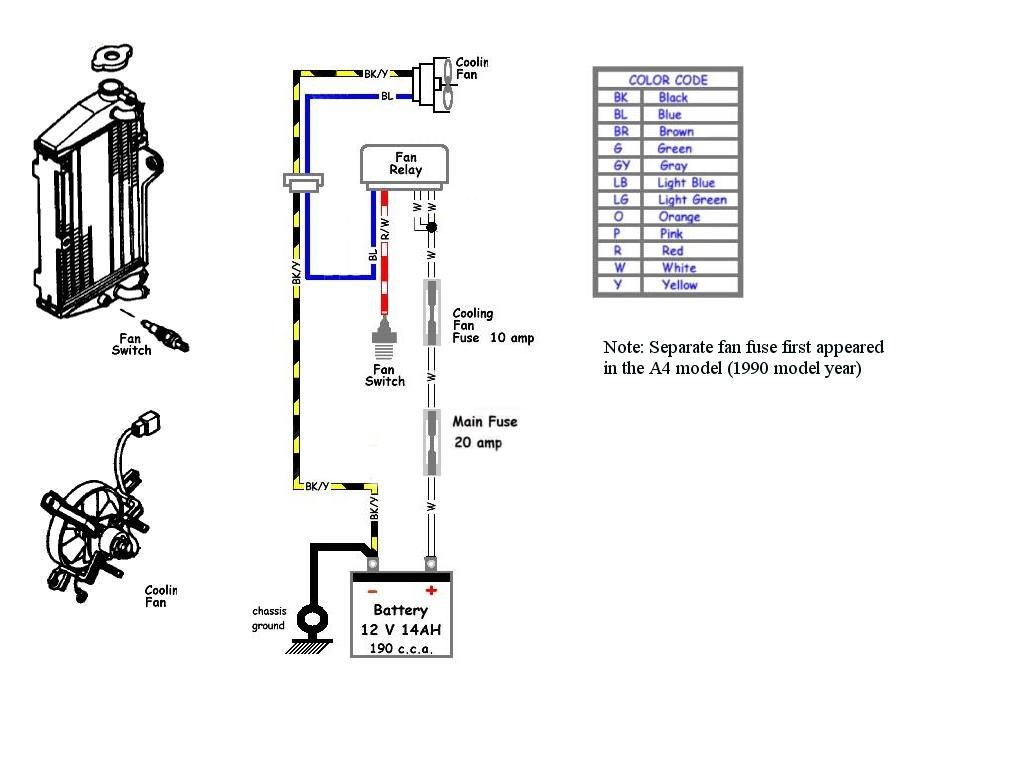
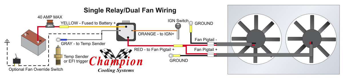
After all we want to help you get back on the road as much as you want to. Then connect switched power usually from your ignition switch to the blue wires on both relays tab 86. Start your wiring project by taking both of the positive wires from the fans and run them to the yellow wires on each relay tab 87. The 12 volts comes from an ignition source the negative connection comes. The cooling fan wiring diagram below is what weve found to be the simplest and most reliable method. The color coded diagram below will correspond with the wires on the relay kit to help simplify the wiring process.
Gallery of Cooling Fan Relay Wiring Diagram