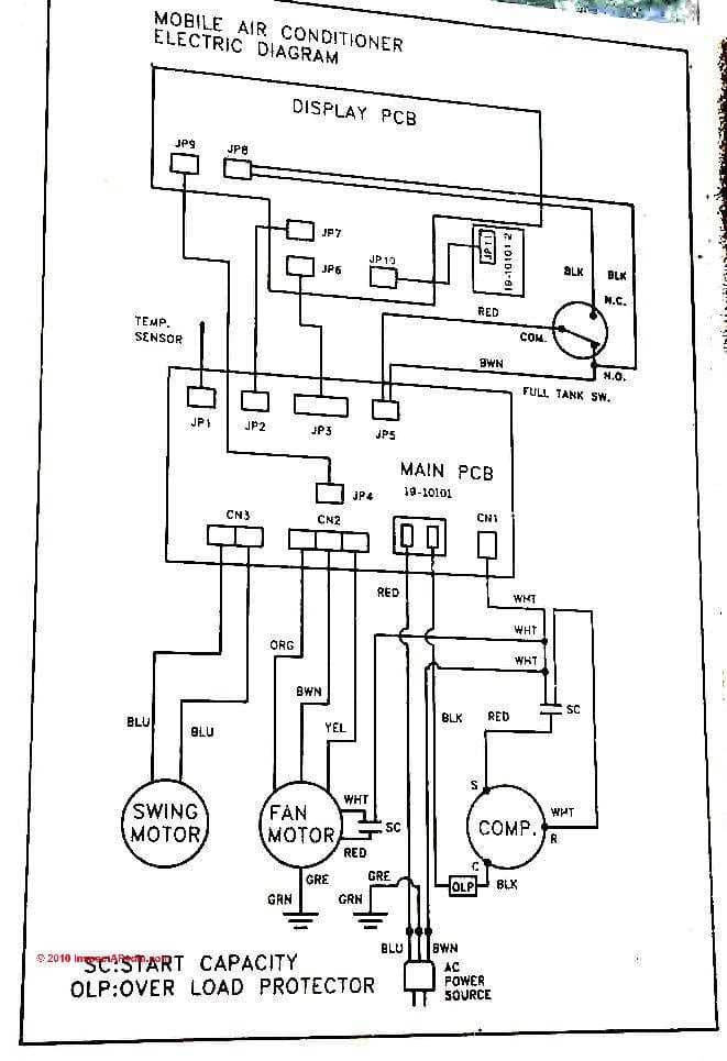
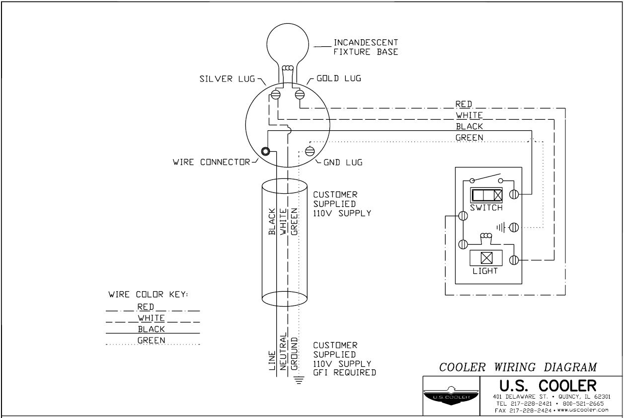
Click on the image to enlarge and then save it to your computer by right clicking on the image. A wiring diagram is a streamlined standard pictorial depiction of an electric circuit.
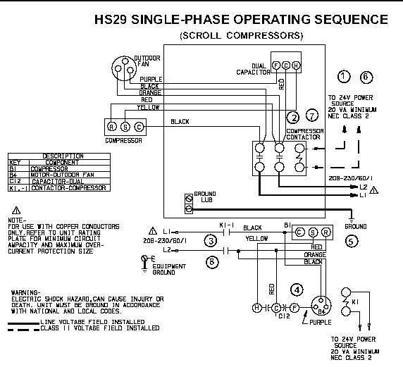
Lennox Hs29 311 Not Turning On Hvac Diy Chatroom Home
Copeland wiring diagram. Getting from point a to aim b. Here is a picture gallery about copeland compressor wiring diagram complete with the description of the image please find the image you need. Each part should be set and connected with different parts in particular way. Copeland compressor wiring diagram. Variety of wiring diagram for copeland compressor. Accordance with the position of the capacitors and relay shown on the wiring diagram.
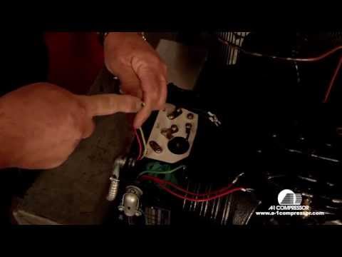
Three phase compressors are connected to. Wiring the sentronic 3 wiring remains the same as previous versions. It shows the elements of the circuit as streamlined forms as well as the power as well as signal connections between the gadgets. Potential relay wiring diagram compressor potential relay wiring diagram copeland potential relay wiring diagram mars potential relay wiring diagram every electrical arrangement consists of various distinct components. A very first look at a circuit layout may be complex yet if you could review a train map you could review schematics. The compressor terminal box has a wiring diagram on the inside of its cover.
If not the structure wont function as it should be. Hvac and refrigeration information links. The objective is the very same. Single phase compressors are connected to the common c start s and run r connections. 61 three phase motor star delta y. It is very easy to miswire a compressor but the results can be deadly.
Wiring diagram sheets detail. Diagram 1a standard control circuit diagram 1b standard control with added alarm circuit diagram 1c. Literally a circuit is the path that allows electricity to flow. Copeland sentronic 3. Before connecting the compressor ensure the supply voltage the phases and the frequency match the nameplate data. Sample wiring diagrams are shown on the following page.
Variety of copeland compressor wiring diagram. There are several wiring schemes depending on control circuit components. Copeland compressor wiring diagram a newbie s guide to circuit diagrams. Copeland condensing unit wiring diagram copeland service manual pertaining to copeland compressor wiring diagram image size 830 x 478 px and to view image details please click the image. All dwm copeland three phase compressors can be started direct on line dol. The positions of the bridges for direct on line start depending on type of motor andor mains voltage are shown on the wiring diagrams.
A wiring diagram generally provides info concerning the family member setting and also plan of tools and terminals on the tools to assist in building or servicing the gadget. Wiring diagram for copeland compressor copeland pressor wiring diagram efcaviation new with.
Gallery of Copeland Wiring Diagram