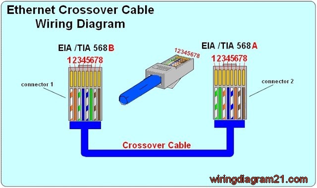
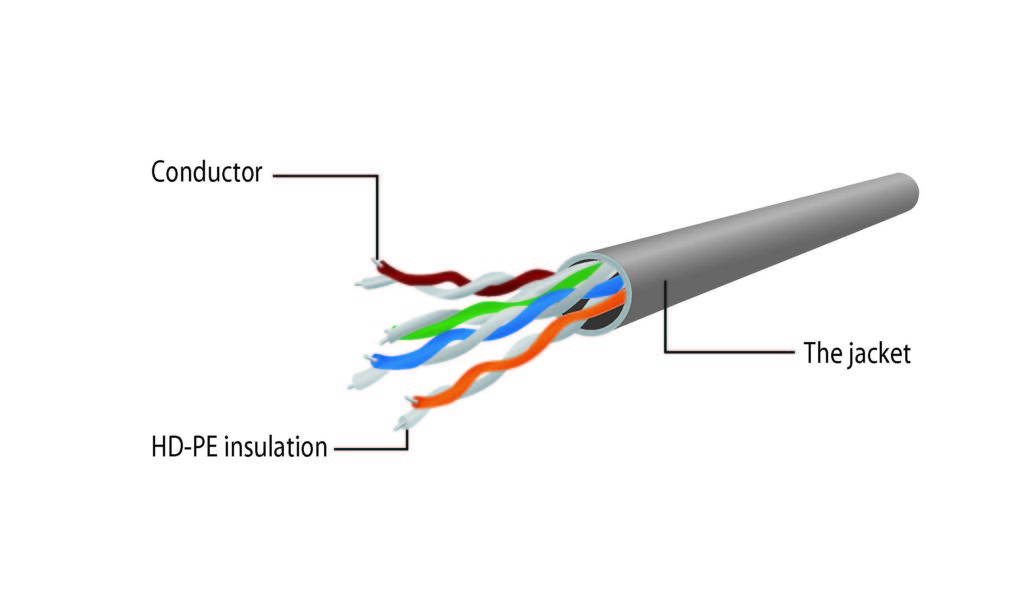
Same parallel power district. Crossover cable wiring diagram we can see in above diagram that left side is following 568b color coding and right end is following 568a color coding.
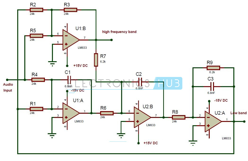
Help Need Help With This Crossover Schematic Diyaudio
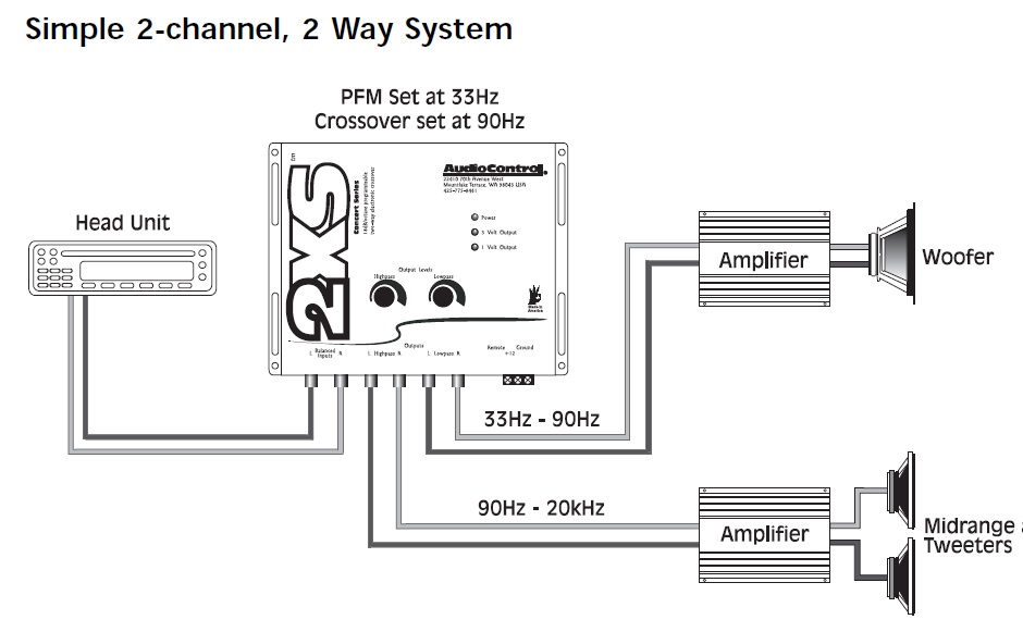
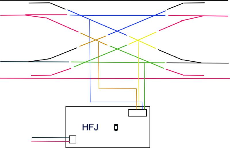
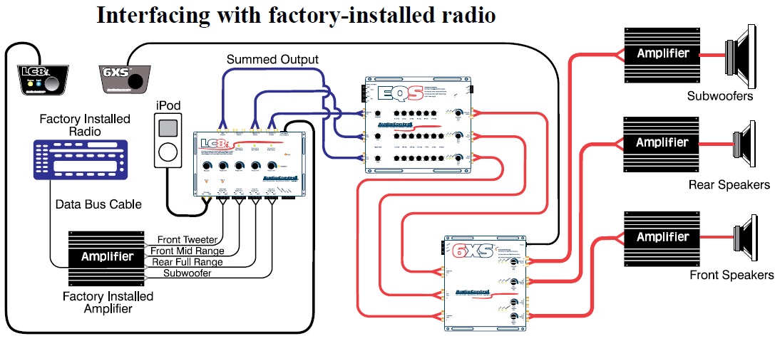
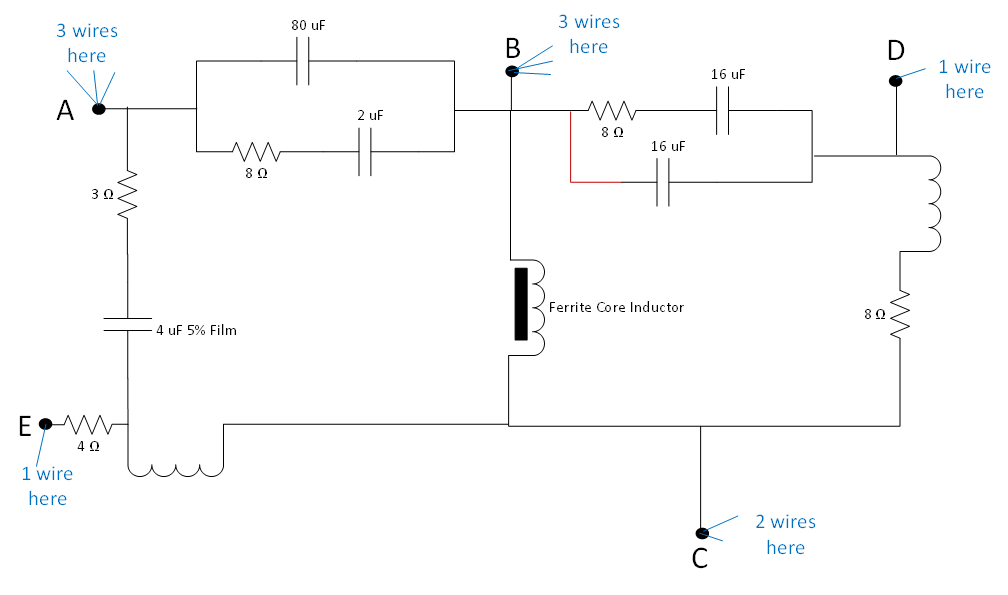
Crossover wiring diagram. In the above diagram the input for the second and third crossover could be directly tied to the main input instead of the high output from another crossover. This means the two routes are totally electrically isolated and you are free to wire them up how you want. Injunction of two wires is generally indicated by black dot on the intersection of 2 lines. But it doesnt imply link between the wires. As stated previous the traces in a speaker crossover wiring diagram represents wires. At times the cables will cross.
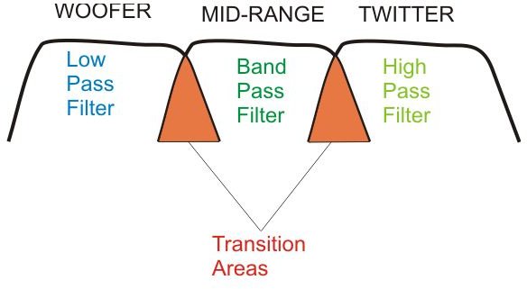
The following ethernet crossover cable diagram represents the wiring for a cat5 and cat5e crossover cable. Crossover cable color code tia 568b following table illustrates tia 568b color coding scheme which is applied on left end of cable in crossover cable wiring diagram. In normal setups youll use a straight through cable where the wires are the same on each side. Although the diagrams in this document show each of the high speakers being run through multiple high pass filters this is not necessary. At a turnout without any reversing loop involved. Cat5 network wire diagram.
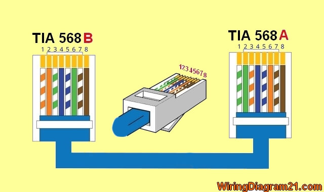
Cat 5 wiring diagram crossover cable diagram. This cat5 wiring diagram and crossover cable diagram will teach an installer how to correctly assemble a cat 5 cable with rj45 connectors for regular network cables as well as crossover cables. The crossover cable diagram shows the transfer and receive wires are crossed this allows the computers to talk directly to each others. Please note that these instructions are the same for cat 6 cable and and other type of 4 twisted pair network cable. This is the most common case where the two routes meet again eg. The diagram above shows a diamond crossing with isolated routes which is fairly typical.
Gallery of Crossover Wiring Diagram