We encourage you to read this manual carefully. A 1 block diagram curtis 12041205 controller a 1 fig.

Solarfest Build Your Own Electric Motorcycle Resources And
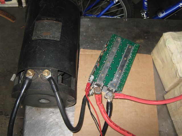
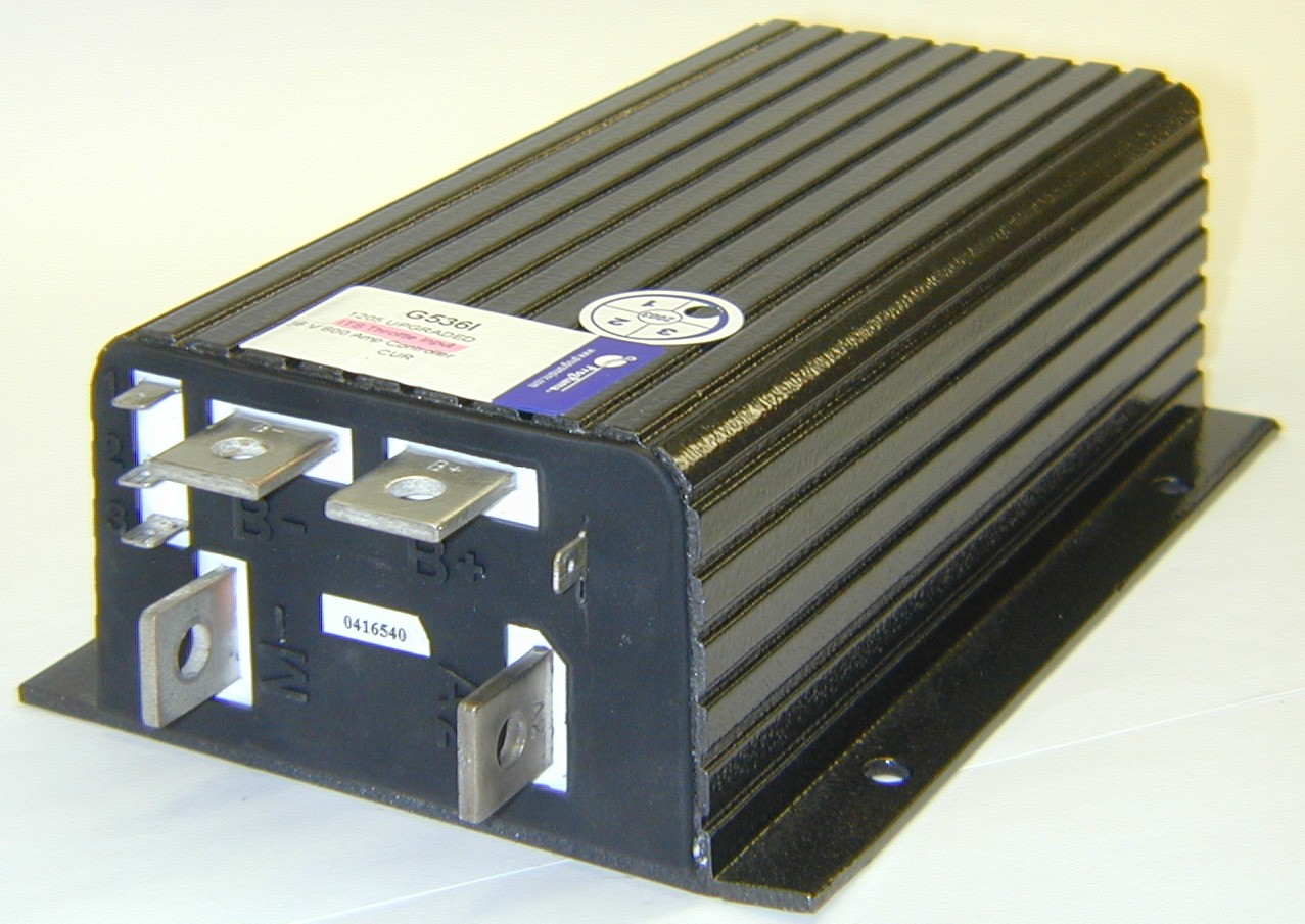
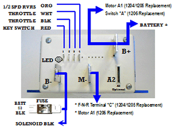
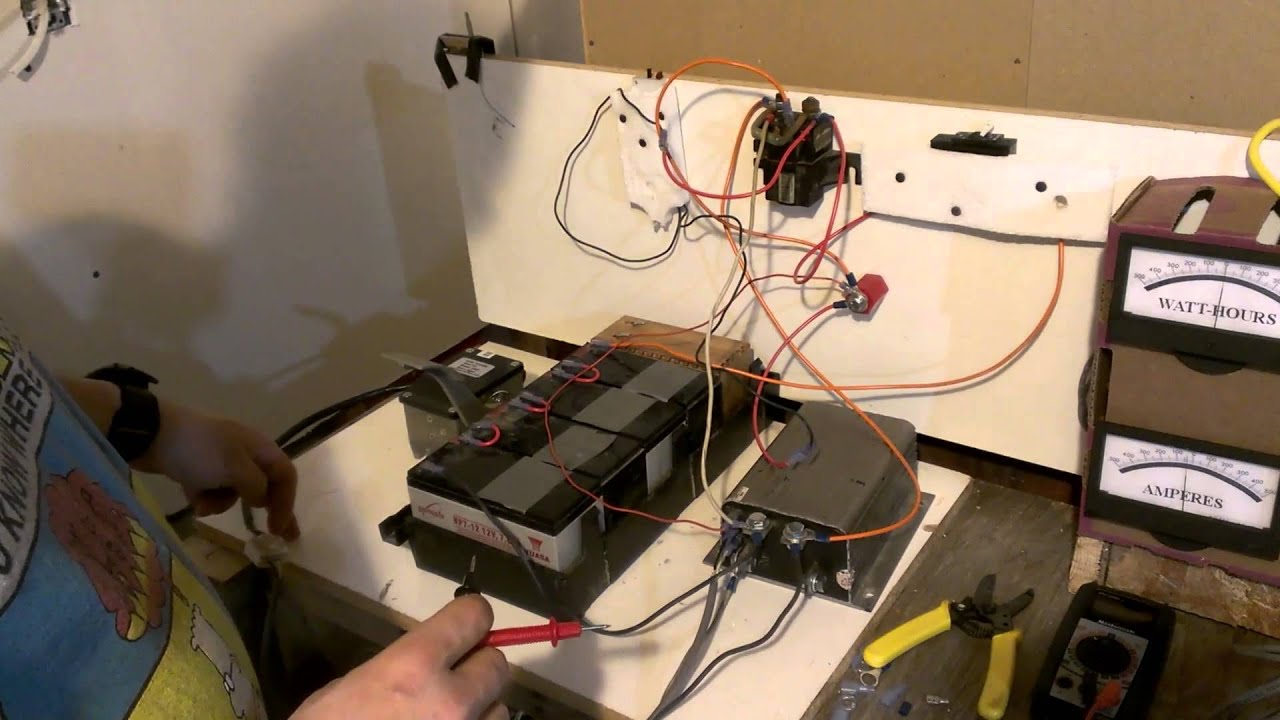
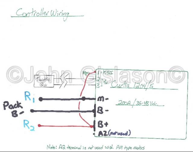
Curtis 1204 controller wiring diagram. 6 curtis pmc 12041205 controller. Curtis controller wiring diagram curtis 1205 controller wiring diagram curtis 1206 controller wiring diagram curtis 1225 controller wiring diagram every electric arrangement consists of various unique pieces. On the pictures below ill show the steps i taken while upgrading the curtis dc motor controller. Curtis 2436v 275a 0 5v pmc 1204 018. Curtis pmc 12041205 manual 1 overview 1 fig. Alternate control wiring to provide freewheeling.
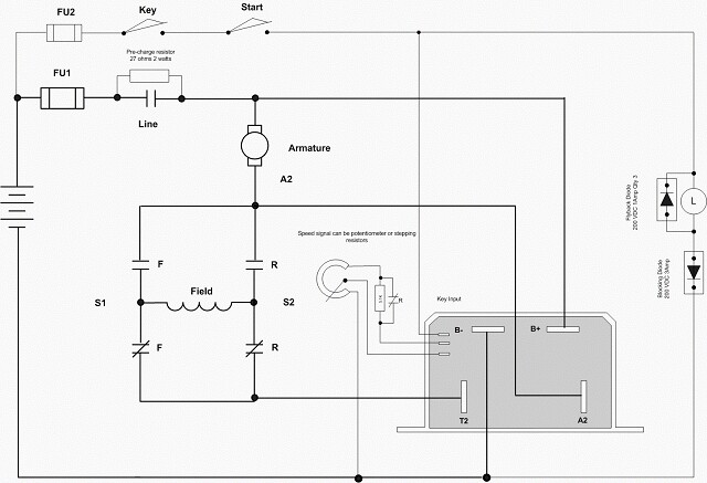
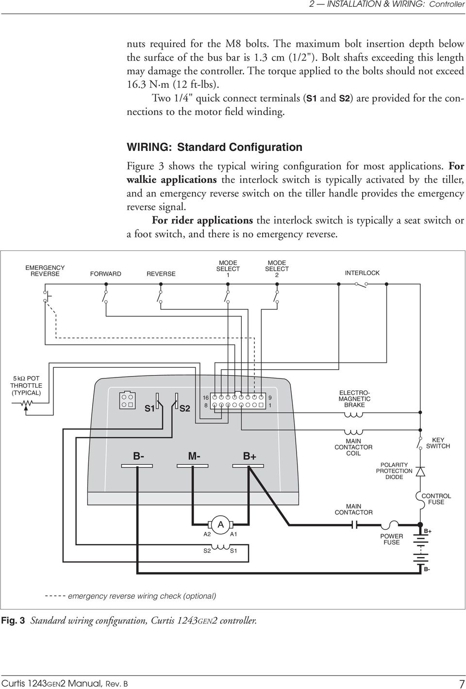
Push on connectors for control wiring familiarity with your curtis controller will help you to install and operate it properly. They are identical except for the wiring at terminal j5. 2 installation wiring. Small vehicle wiring schematic. 1 curtis pmc 1205 electronic motor controller. B 1 pulse width modulation.
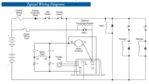
It consists of guidelines and diagrams for various varieties of wiring techniques as well as other things like lights home windows and so forth. Forwardreverse with standard power wiring 11. Reversing contactor diagrams for kelly controllers. Forwardreverse with standard power wiring field. Curtis 1204 controller wiring diagram wiring library curtis controller wiring diagram wiring diagram contains several in depth illustrations that display the relationship of various things. Basic configurations two basic wiring diagrams are shown.
4 basic wiring diagram curtis 1204m05m09m21m with active main contactor. 01012019 01012019 0 comments on curtis 1204 controller wiring diagram. Below is the picture of typical wiring diagram for the club car controller. Standard wiring diagrams controller wiring. Model 1204 has identical connections. Wired this way the vehicle will plug brake if the direction is changed with the vehicle moving and the throttle applied.
Standard wiring diagrams controller wiring. Overview curtis pmc model 1204 and 1205 electronic motor speed controllers are designed to provide smooth silent cost effective control of motor speed and torque on a wide variety of industrial electric vehicles. In the configuration in figure4 the main contactor driver is active. Curtis controllers model 1204. Pm a 36v48v dc motor controller replacing curtis m pm. 2 installation wiring.
4 basic wiring diagram curtis 1204m05m09m21m with active main contactor. Curtis 1204 controller wiring diagram. Curtis 2436v 275a pmc 1204 016 price. They are identical except for the wiring at terminal j5. Please note that this controller uses a 3 wire 5k pot. If not the structure will not work as it should be.
Basic wiring configuration fig. Basic configurations two basic wiring diagrams are shown. In the configuration in figure 4 the main contactor driver is active. The second end is tied to b. Each part should be set and connected with different parts in specific manner. Block diagram curtis pmc controller.
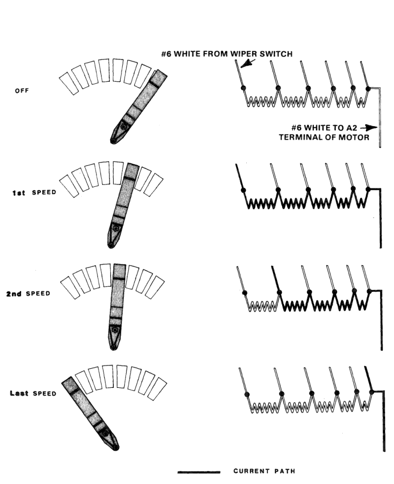
The wiper and one end of the pot is connected to the controller. Series motors figure 6 is a schematic of the configuration shown in figure 5.
Gallery of Curtis 1204 Controller Wiring Diagram