This is probably true but i still feel a little uncomfortable about it. Wiring unlimited is now available.
Passive 4 20ma Signal Isolation Conditioner Din11 Iap 100lp
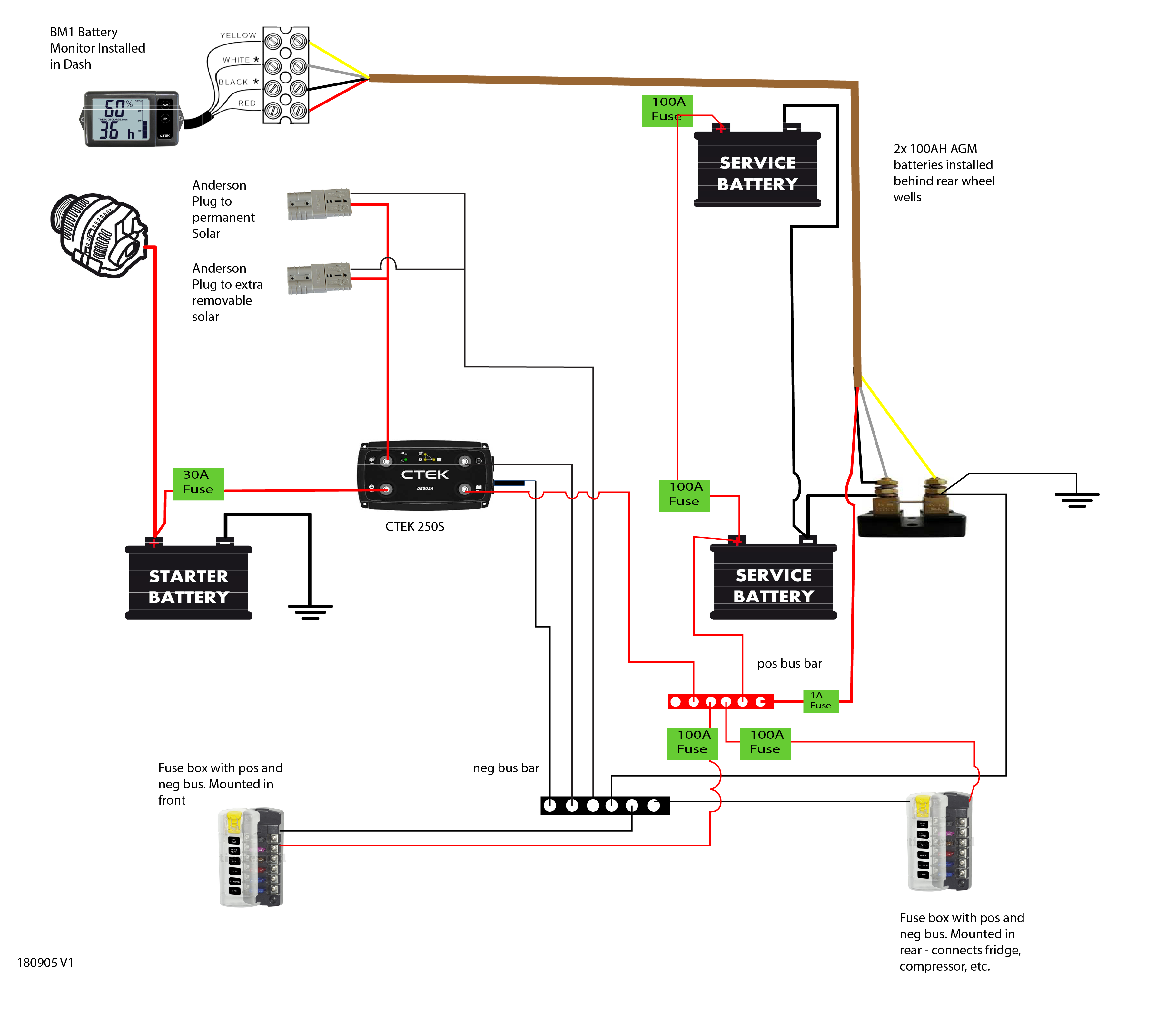
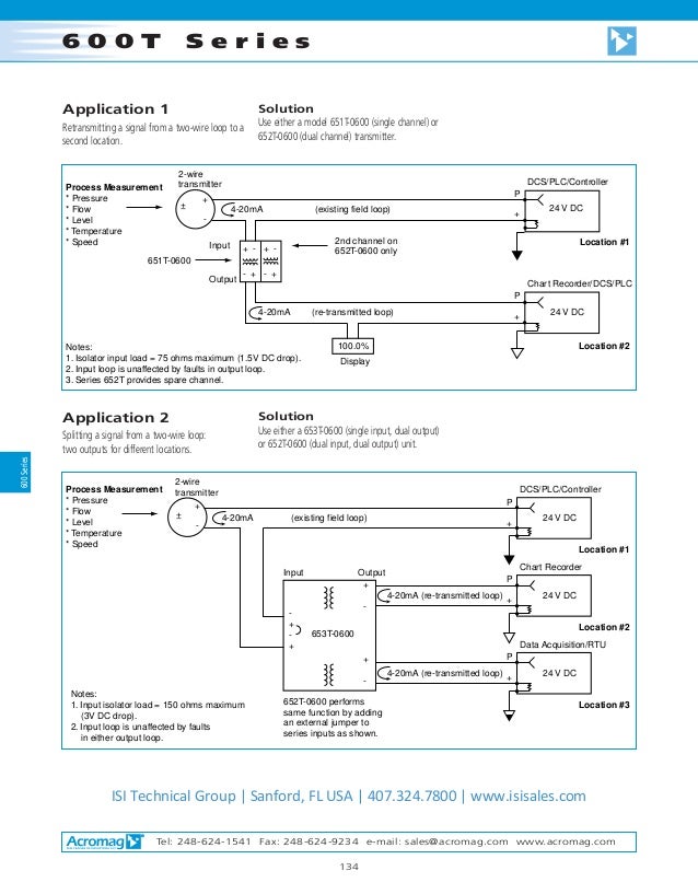
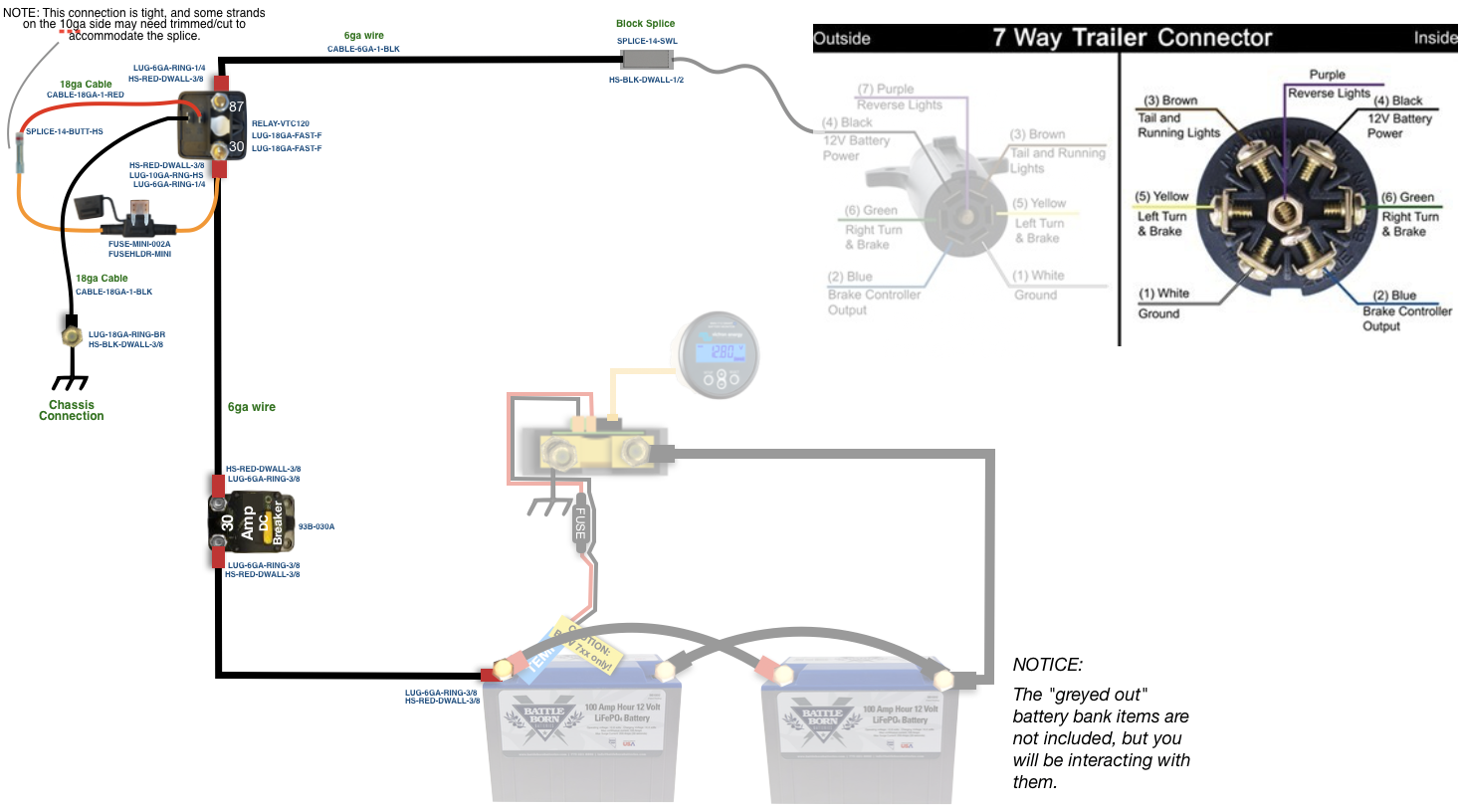
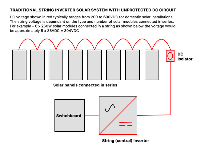
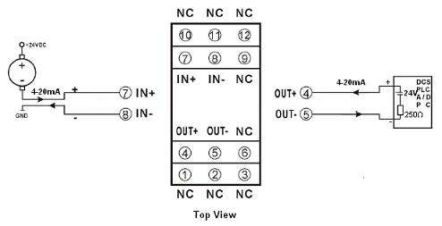
Dc isolator wiring diagram. Wiring unlimited is all about electrical wiring of systems containing batteries inverters chargers and inverterchargers and going by the testaments on the victron community an invaluable. Above is a diagram of my 12 volt wiring. Wiring diagram of loop powered isolator with external powered 4 wire transmitter. Switchisolator both on the roof and next to the inverter does not address the lethal accumulated dc. Switchisolator does nothing to stop the generation of the lethal dc. However the flexibility of these dc isolators introduces instances of incorrect wiring when manufacturers specifications are misunderstood resulting in dc isolators being underrated for the.
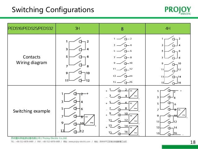
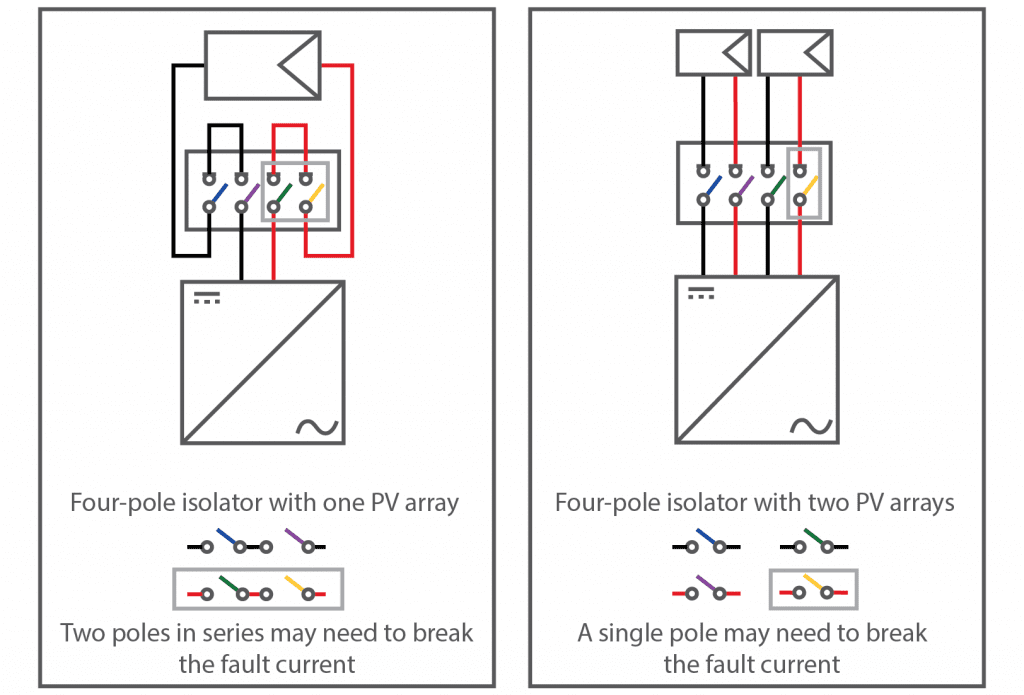
Justin case solar power and bush camping 7690 views. Please read text below. Diagram 2 2 2 2 for example diagram 24 below is how the wiring should be completed for no. Dc isolator switch 32 max rated current 32. Voltages required for solar generation. Pv dc isolator switches pv dc isolator switches dimensionsmm switching configurations wiring diagram contacts wiring diagram poles in series number of strings type number weight kgpcs contacts wiring graph switching example 2 pole 4 pole with input on top output bottom 4 paralleled poles type 2 pole 4 pole 4 pole with input and output bottom.
A victron energy book by margreet leeftink information developer for victron energy bv. Solar photovoltaic pv systems use rotary dc isolators with multiple current and voltage ratings more commonly than dc rated circuit breakers. Wiring unlimited enpdf what is wiring unlimited. The placement of this dc. You can see in the above circuit diagram the pin 1 and 2 of the optocoupler are connected to a dc source through a switch and a resistor. Din rail mounting 3.
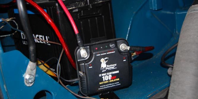
Here the photo diac optocoupler is used to trigger the triac. Download it for free here. Wiring in a dc isolator switch. In addition the battery isolator will drop the alternator voltage by about 03 volt actual measurement further providing protection. 32 a 2 series 2. Voltage within the panels and associated wiring outlined in red on the diagram below.
The motor is connected to the ac supply through a triac. This is a typical wiring diagram of a loop powered signal isolator get energy from the input and 4 wire transmitter detailed parameters of loop powered signal isolator ato s sinir 502e are in the product page. Wiring the new dc disconnect duration. The diagram below shows the conventional placement of the dc. Din rail mounting door clutch all voltage and current are labeled on product 600 v 32 a 800 v 32 a 1000 v 13 a 1200 v 13 a see wiring instructions contacts wiring diagram adis series pv dc isolator switch pvdc isolator switches version.
Gallery of Dc Isolator Wiring Diagram