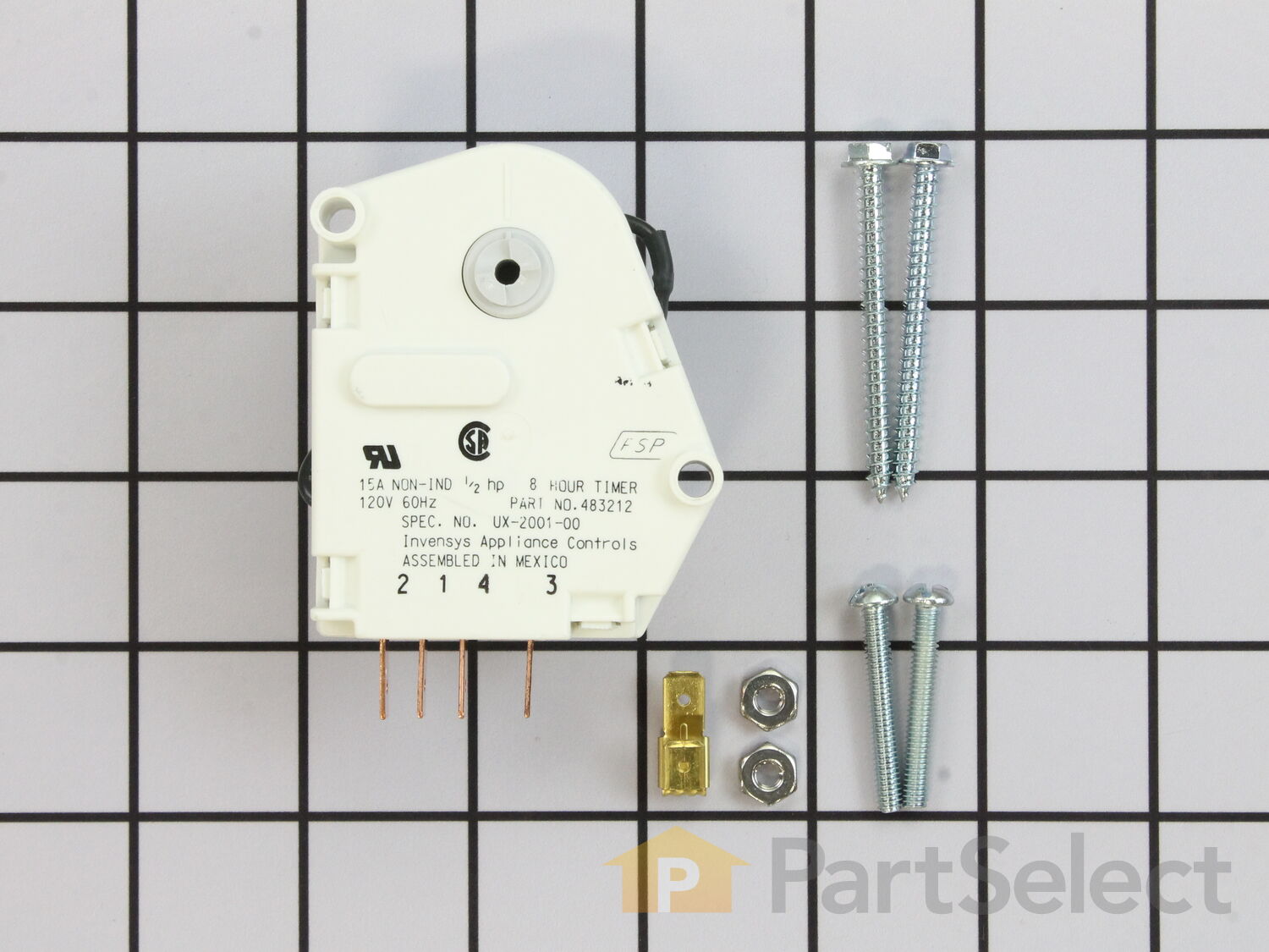
Here is a picture gallery about 20 wiring diagram complete with the description of the image please find the image you need. How to diagnose a defective freezer defrost time clock.

Paragon Timers And Manuals
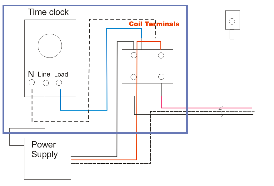
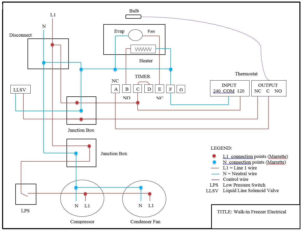
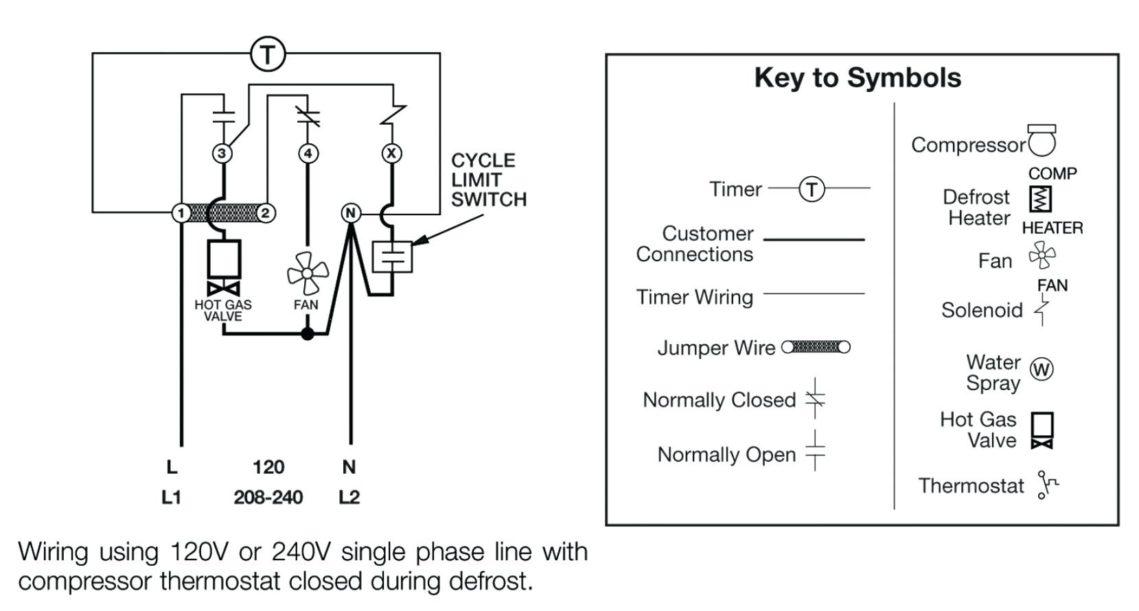
Defrost clock wiring diagram. July 10 2018 by larry a. Clock as this may cause permanent damage to the clock. Caution default wiring diagram f 3 1 2 4 n x t stat fan defrost 120 heater vac l1 l2 defrost thermostat w fan delay k1 k2 swith position mode a. A wiring diagram is a streamlined standard pictorial representation of an electrical circuit. Applications and wiring diagrams. Paragon 8141 00 wiring diagram download defrost clock wiring diagram and freezer timer to paragon 8145 20.
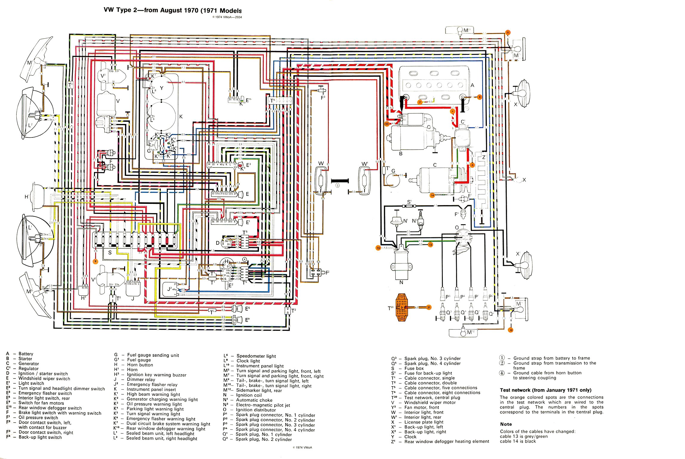
Allied refrigeration 440 823 5720 cleveland ohio. Defrost timers and residental i challenge anyone to read those wiring diagrams however. Defrost timer wiring diagram bestharleylinksfo. A wiring diagram is a streamlined standard pictorial depiction of an electrical circuit. A wiring diagram is a simplified traditional photographic depiction of an electrical circuit. The defrost timer is operated by a single phase synchronous motor like those used to operate electric wall clocks figure 281.
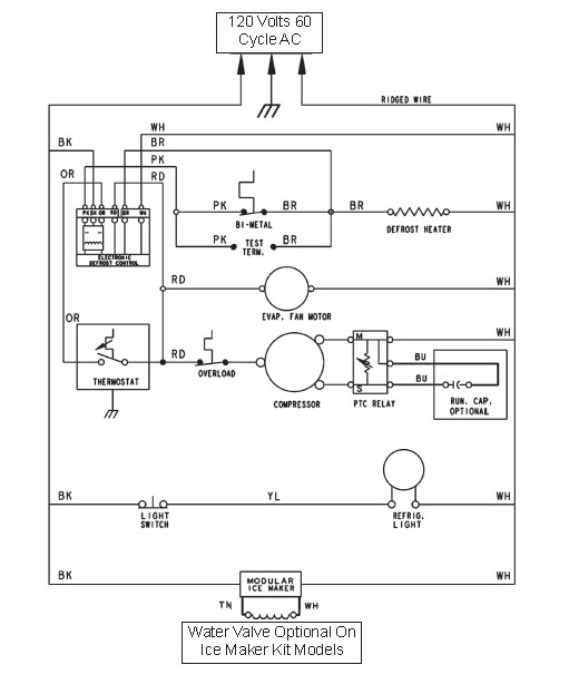
Last edited by icemeister. Collection of paragon defrost timer 8145 20 wiring diagram. It shows the elements of the circuit as streamlined forms and also the power and also signal links in between the devices. Single condenser defrost time clock board pn 604 3047 document part 026 4834 rev 1 12 nov 2013 page 6 of 7. Figure 5 typical evaporator wiring diagram after installation installation instructions. A schematic drawing of the timer is shown in figure 282.
I had to replace. Variety of walk in freezer defrost timer wiring diagram. Wiring diagrams for thread. Paragon defrost timer wiring diagram paragon defrost timer wiring regarding 20 wiring diagram image size x px and to view image details please click the image. It reveals the elements of the circuit as streamlined shapes and also the power as well as signal links in between the tools. The contacts are operated by a cam that is gear driven by the clock motor.
I remove a bad grasslin time clock and replace it with a paragon time clock. Defrost clock wiring diagram and freezer timer to paragon 8145 20. Defrost clock wiring diagram and freezer timer to paragon 8145 20. Assortment of refrigerator defrost timer wiring diagram. It shows the components of the circuit as simplified forms and also the power as well as signal connections in between the gadgets.
Gallery of Defrost Clock Wiring Diagram