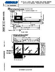
Pvc steel pneumatic tube 4½ off sets. Vat 21gx pharmacy installation with cctv.

Ep2400417b1 System For Tracking End User Electronic Content
Diebold vat 21 wiring diagram. Refer to the following list to determine the appropriate wiring diagram for the item you are installing. Observe the wiring diagram to ensure the wire colors are properly mated to the appropriate number on the terminal strip. Figure 8 7 interconnect cable connections. Vat 12 operating instructions. Diebold 816 audio switcher cca 41 017127 000b and 41 017127 000c and power supply assembly 41 019986 000a. Refer to diebold vat tubing parts requirements.
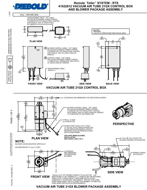
Vat 21 operating instructions. Vat 21gx system blower detail hard wired install. Vat 21gx customer unit locations. Easy aire 10 and vat 30 operating instructions. Tp 821421 001b easy aire 10gx and vat. Vat 21gx typical audiovideo schematic.
See figure 8 9 for a wiring diagram showing connections at a dual sided operator unit. Operating instructions for vat 23 with an overhead customer terminal. Vat 21gx installation guide diebold nixdorf. 91 200170 0062 by diebold nixdorf foil shields with drain color coded 3 shielded twisted pairs individual 20 cauge stranded tinned copper audio cable dd cable by diebold nixdorf 14 0 29 016865 000a cable 4267 meters rj 45 interconnecting 10 0 by diebold nixdorf power cable 41 019525 000a vat video matrix switcher by. Vat 21gx customer unit locations tandem. Vat 23 overhead customer to upsend operator installation manual.
Blower power supply wiring. Test meter probes 1mm dia. 00 013656 000a is designed for use with comm master audio. Diebold 816 audio retrofit kit for vat 21 vat 23 vat 30 and easy aire 10 with comm master audio. Make sure that the stranded shields are tightly wound with no loose strands. Cctv for vat systems customer and operator units optional online video advertising controller.
Figure 8 6 blower wiring connections. Refer to figure 6 5 for a wiring diagram for a system with an overhead customer unit to upsend operator unit. The power supply and cca are mounted into separate housings. See figure 8 8 for a wiring diagram of the complete system equipped with the standard operator unit. Using phoenix connectors for the vat 23 interconnect cable the interconnect cable 91 152053 6262 for the vat 23 must be cut to length at the job site.
Gallery of Diebold Vat 21 Wiring Diagram