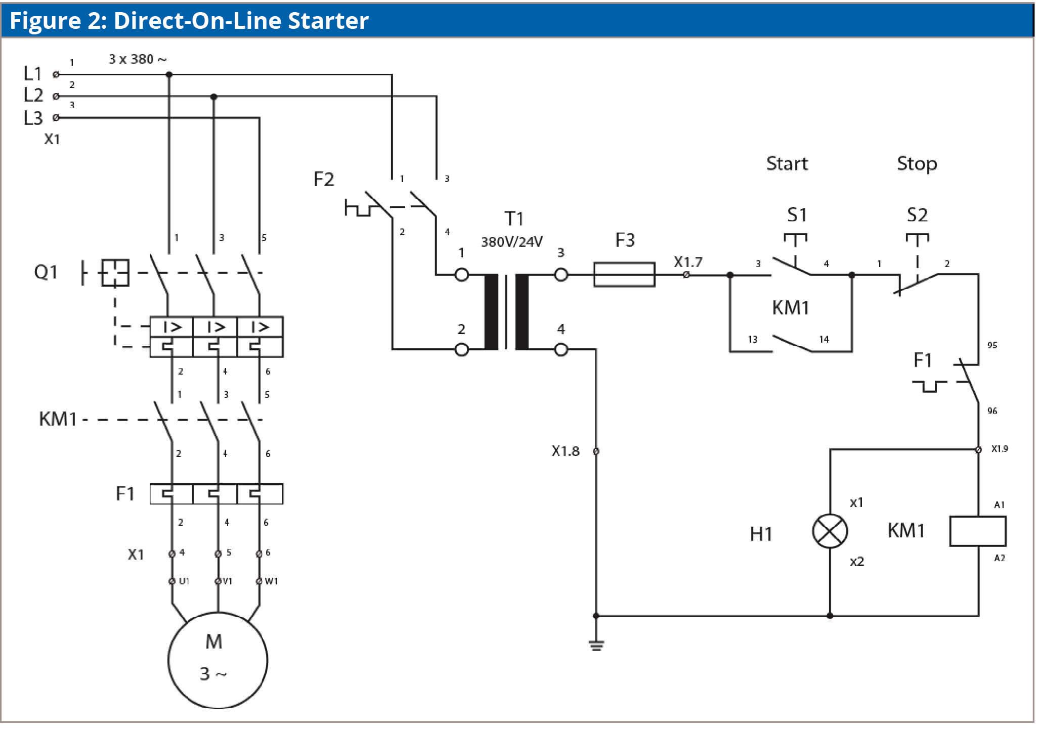
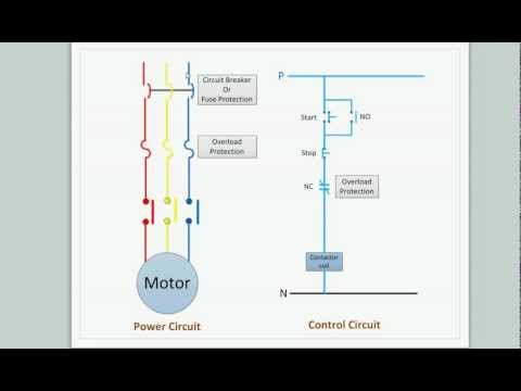
Since the dol starter connects the motor directly to the main supply line the motor draws a very high inrush current compared to the full load current of the motor up to 5 8 times higher. In the below dol starter wiring diagram i shown a molded case circuit breaker a magnetic contactor normally open push button normally close push button switch thermal overload relay motor trip indicator and 3 phase motor.

Direct On Line Starter Electrical Notes Amp Articles
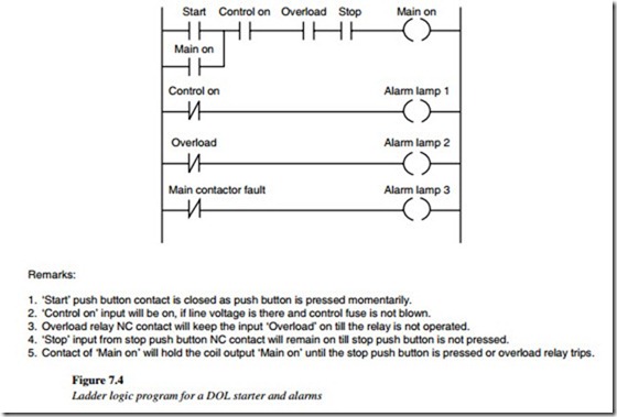
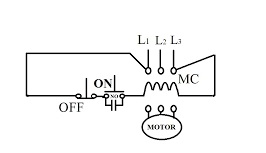
Dol starter control wiring diagram. Dol starter control circuit diagram consist components like main power contactor start button stop push button and overload relay is connected in series this circuit is called control circuit of dol motor starte r. Contactor is connecting among supply voltage relay coil and thermal overload relay. L1 of contactor connect no to r phase through mccb. Wiring of the direct on line dol motor starter 1 three phase supply 230volt coil see wiring diagram. A wiring diagram is a streamlined standard pictorial representation of an electric circuit. Wiring of dol starter 1.
This is the wiring diagram of a dol starter mccb or circuit breaker. Figure shows the conttrol diagram of the dol starter as you have seen in the diagram the starter contains a miniature circuit breaker for the incoming supply protection. The value of this large current decreases as the motor reaches its rated speed. All controlling of starter are controlled by this circuit. Akrtechnical dolstartercontrolwiring hi i am abhilash k r welcome to our malayalam youtube channel akrtechnical. A2 14 18.
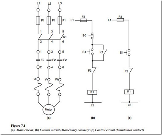
And one wiring is called controlling wiring. 1 the following links are pre fitted to the starter. The r y and b phase are connected through mccb to the contactors. In the above three phase dol starter wiring diagram. An over load relay for the protection of motor against over voltage under voltage single phasing over current etc. 13 17 with a flying lead to be connected to overload terminal 95.
It shows the elements of the circuit as streamlined shapes and the power and signal links in between the tools. A wiring diagram normally provides details regarding the loved one position as well as plan of tools and also terminals on the tools to assist in building or servicing the gadget. All other control and power connections have to be made by the installer. L2 of contactor connect no to y phase through mccb. Dol starter control power wiring diagram overload indicator wiring in malayalam. The contactor has 3 types of contacts.
Assortment of motor starter wiring diagram pdf. L3 of contactor connect no to b phase through mccb. A wiring diagram of a dol starter is shown below.
Gallery of Dol Starter Control Wiring Diagram