All controlling of starter are controlled by this circuit. The coil of the contactor is 380 vac.

Lk 5821 Push On Motor Contactor Wiring Diagram Schematic Wiring
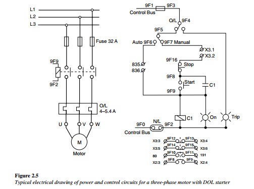
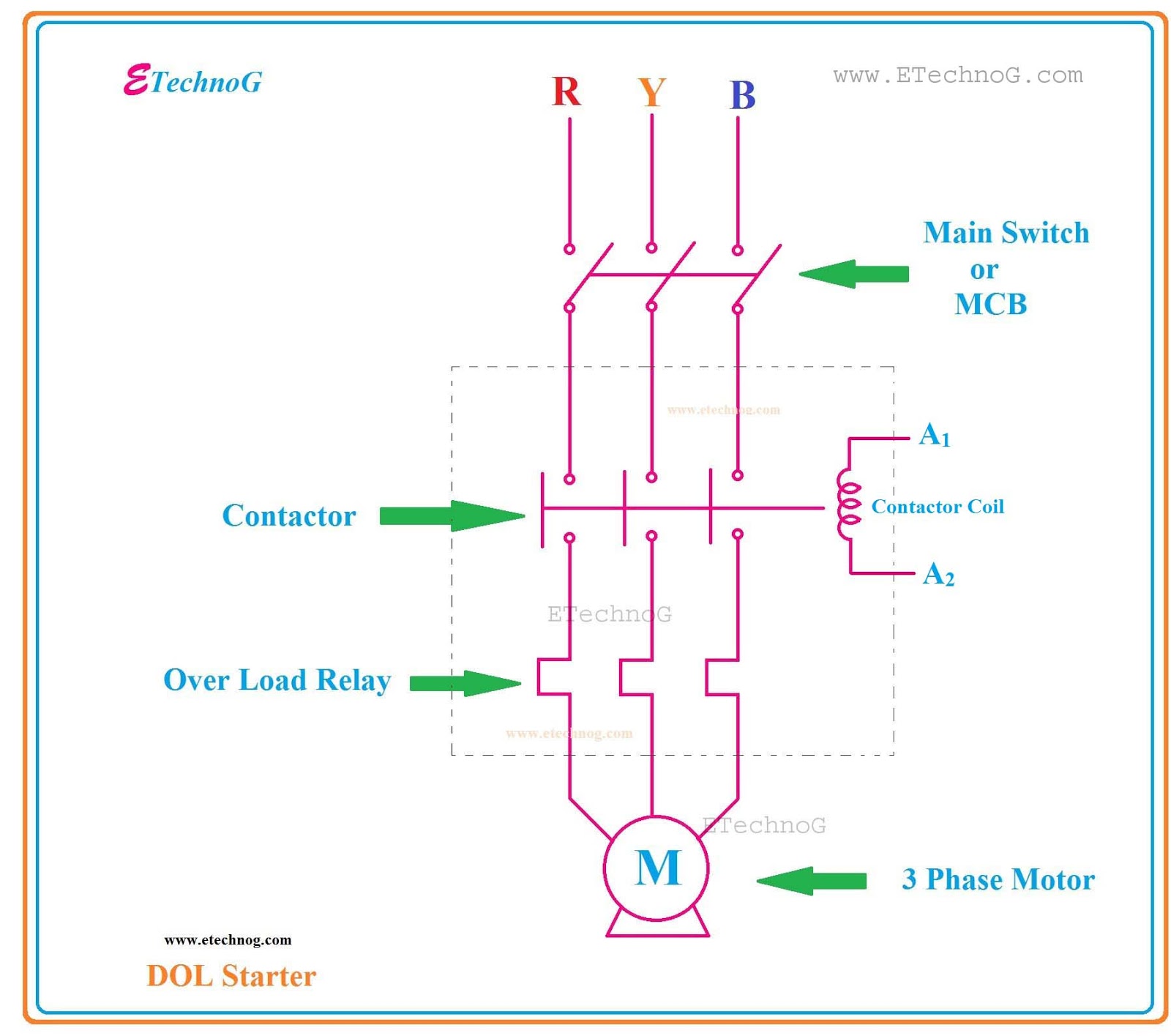
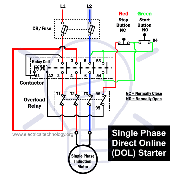
Dol starter wiring diagram. A single phase dol motor starter can be designed using the same components as shown in following diagram. Dol starter control circuit diagram consist components like main power contactor start button stop push button and overload relay is connected in series this circuit is called control circuit of dol motor starte r. Dol starter power circuit diagram. The contactor connection with thermal overload relay and the motor connection with overload relay is shown. Dol starter wiring diagram for three phase motor. We connect the circuit breaker contactor and overload relay in series between electrical supply and motor as shown in below diagram.
The wiring diagram for a dol stater is shown below. We have to use all 3 poles of the overload relay otherwise the imbalance due to the current flow in only 2 of them will cause unnecessary tripping. And the normally open and normally close push button shown. In the above dol starter diagram. A direct online starter consits of two buttons a green button for starting and a red for stopping purpose of the motor. Single phase dol starter wiring diagram.
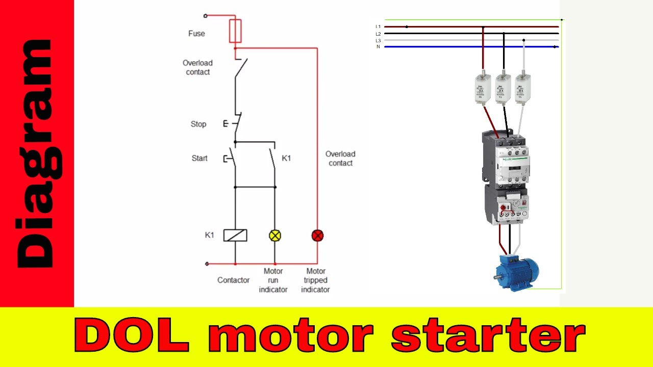
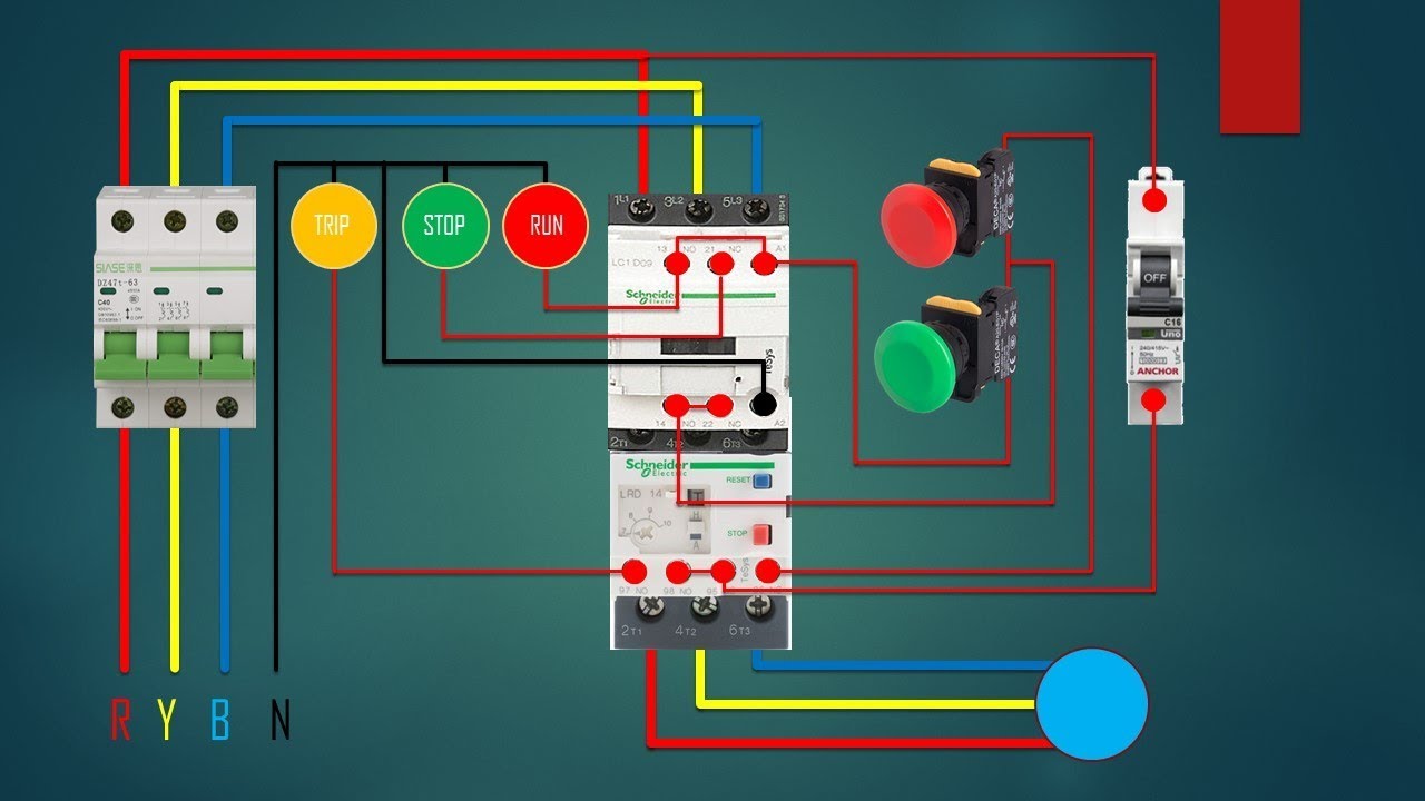
The dol starter comprises of an mccb or circuit breaker contactor and an overload relay for protection. Dol starter wiring diagram. To wire a 3 phase motor the first thing to wire is a circuit breaker which is disconnect and connecting point then we will get the supply from circuit breaker and connect supply to contactor or starter and then to overload relay. And one wiring is called controlling wiring. The ryb is the three phase 380 volts supply. In the above three phase dol starter wiring diagram.
In the below dol starter wiring diagram i shown a molded case circuit breaker a magnetic contactor normally open push button normally close push button switch thermal overload relay motor trip indicator and 3 phase motor.
Gallery of Dol Starter Wiring Diagram