Assortment of dpst rocker switch wiring diagram. In other words its like two simple switches controlled by a single actuator.

Waterproof Miniature Illuminated Rocker Switch Ip65 Spst
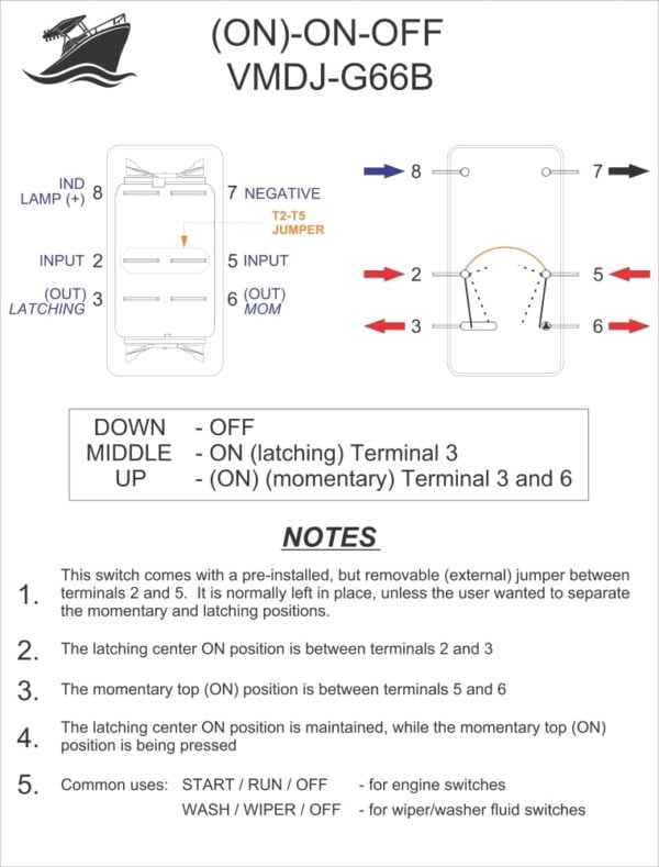
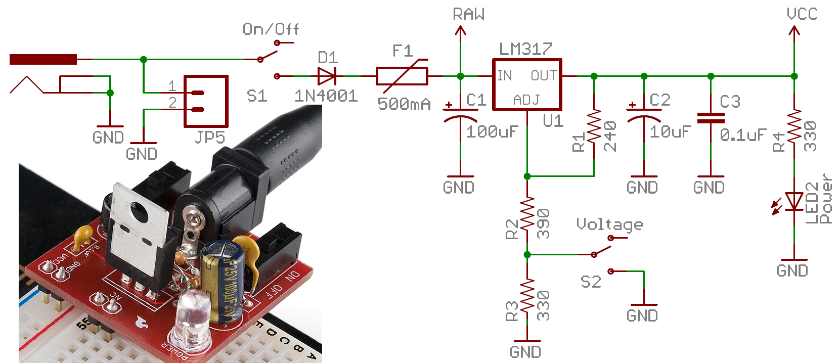
Dpst toggle switch wiring diagram. When the switch is connected one way for circuit a and circuit b the lamp and led will both be on. It shows the parts of the circuit as streamlined shapes and also the power and also signal connections between the gadgets. Below is an example of a circuit which utilizes a double pole single throw switch. You can see above how a double pole single throw switch can be used to put a circuit in any of 1 of 2 modes. A dpdt toggle switch has 6 terminals. St switches close a circuit at only one position.
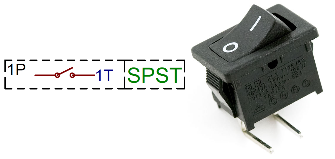
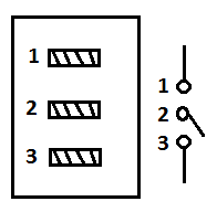
A wiring diagram is a simplified conventional pictorial depiction of an electrical circuit. We will now go over the wiring diagram of a dpdt toggle switch. Below is the schematic diagram of the wiring for connecting a dpdt toggle switch. Terminals 3 and 4 represent the toggle switch. The dpst switch for example has four terminals but it is a dp not a 4p switch. A double pole single throw dpst switch controls the connections to two wires at once where each wire only has one possible connection.
The other position of the handle is off. Throw refers to the extreme position of the actuator. Dt switches close a circuit in the up position as well as the down position on on. Double pole single throw switch dpst circuit. Dpdt toggle switch wiring.
Gallery of Dpst Toggle Switch Wiring Diagram