They are basically the same. Programming the drok digital time delay relay to get the drok digital time delay relay to work one must first set the onoff times then select which timer mode p0 0 or p1 5 to use.

Drok Dc Dc Buck Voltage Converter 4 5 40v 12v To 5v 2a Step
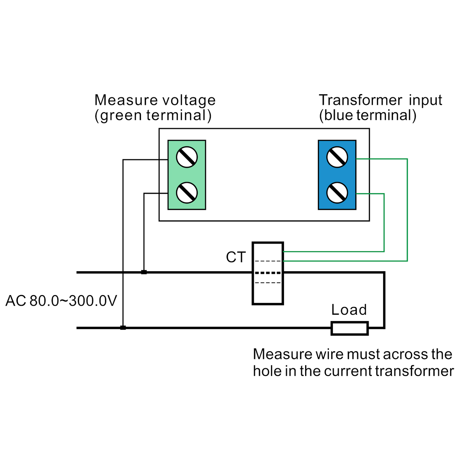
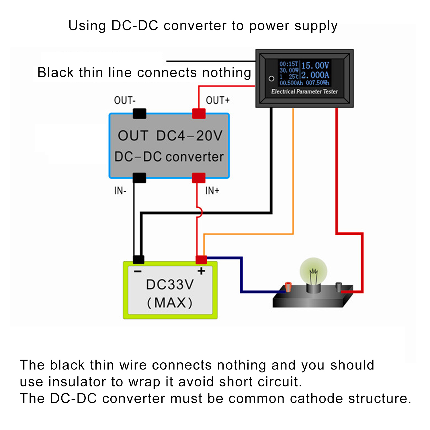
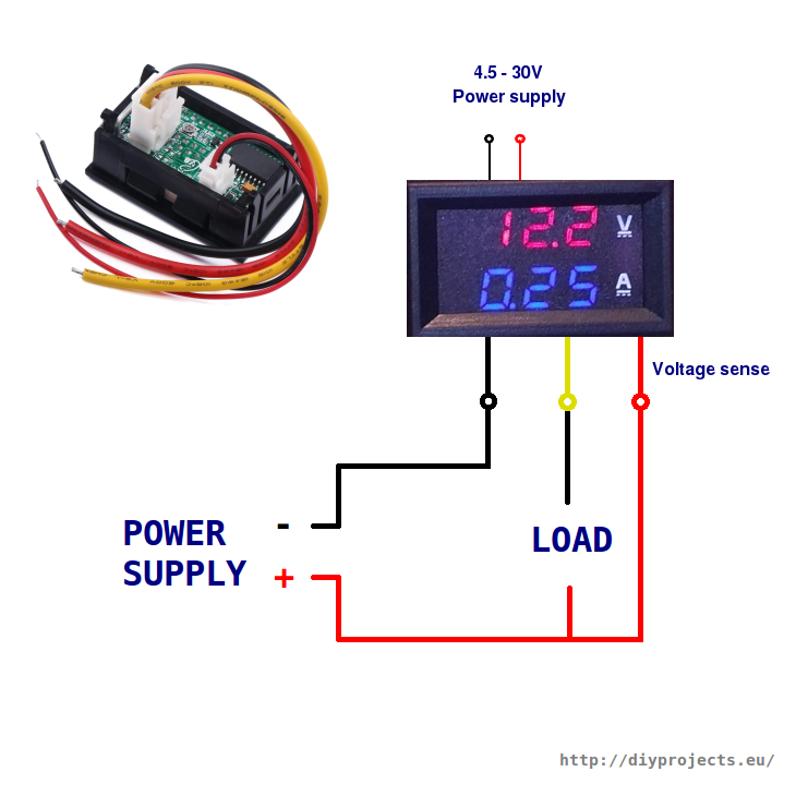
Drok wiring diagram. Step by step programming guide for drok xy lj02 relay time. It shows the components of the circuit as simplified shapes and the aptitude and signal connections amid the devices. I had a hard time getting the proper display in getting a reading from a aa battery using an isolated 10v supply for the meter. Generac generator wiring diagram collections of briggs and stratton power products 1006 1 megaforce 6500 parts. Learn arduino from a proven instructor with 100s of projects code wiring diagram in structured course in one place. This a great.
There is a connector with thick wires and connector with thin wires. Multifunctional drok signal generator kit is able to generate ampere voltage by one module which generate 04 20ma current signal and 0 10v voltage signal just by rotating a multi cycle precise potentiometer simple and handy. Pay attention to the wiring diagram among the description pictures. Eye on stuff please consider donating to my channel so i can make more videos for you. Supplier drok handled the problem very professionally so i will continue to purchase products from him. Also there is some type of wiring instructions in the product description section.
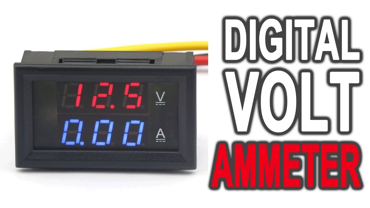
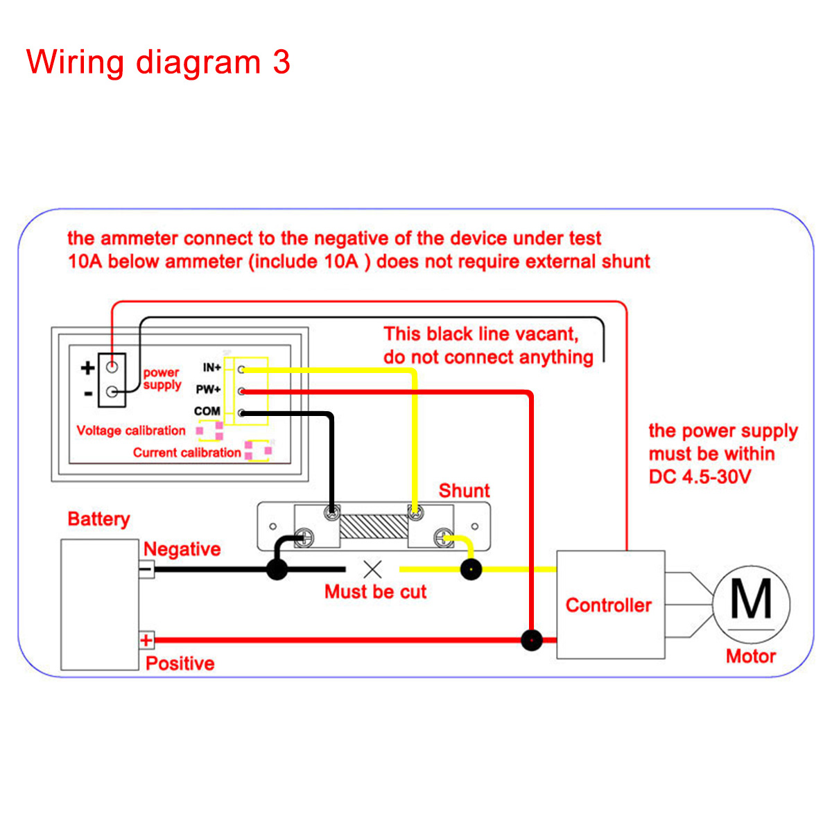
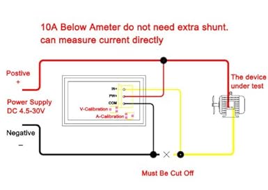
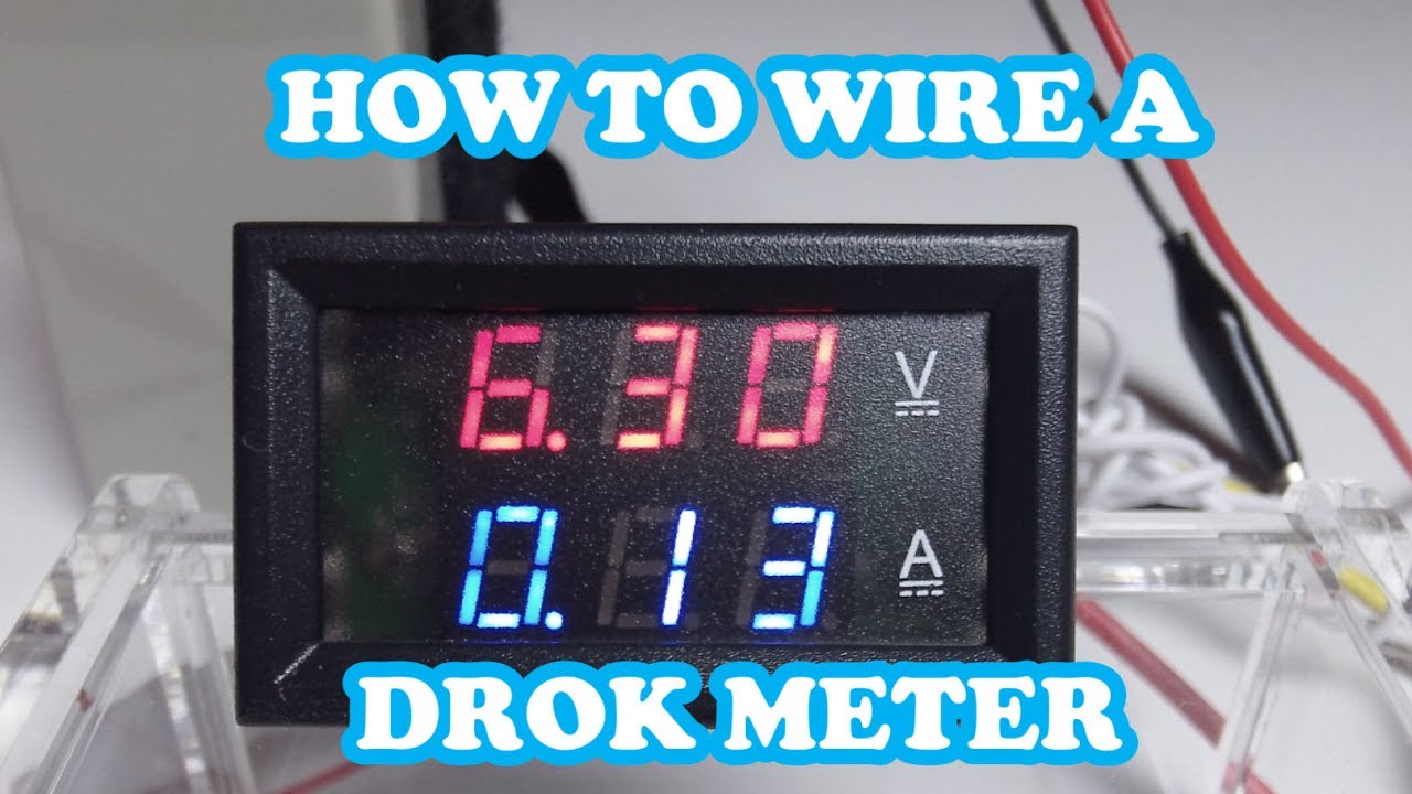
Generac generator transfer switch wiring diagram image. In this video i show you how to wire up the drok 10amp 100vdc meter. 4390 generac generator wiring schematic simple electronic. Drok wiring diagram wiring diagram is a simplified good enough pictorial representation of an electrical circuit. But coloring of wires vary. You need a wiring diagram with an external shunt instead.
Generac ats wiring diagram download. Amp volt dual signal generator. Following is the method i used to program the timer. Also when measuring current that exceeds 10a which can be handled with the internal one. Wire this up to an m12 sensor cable and this can be used out in the field to. Amperage measurement is done by passing power through.
Gallery of Drok Wiring Diagram