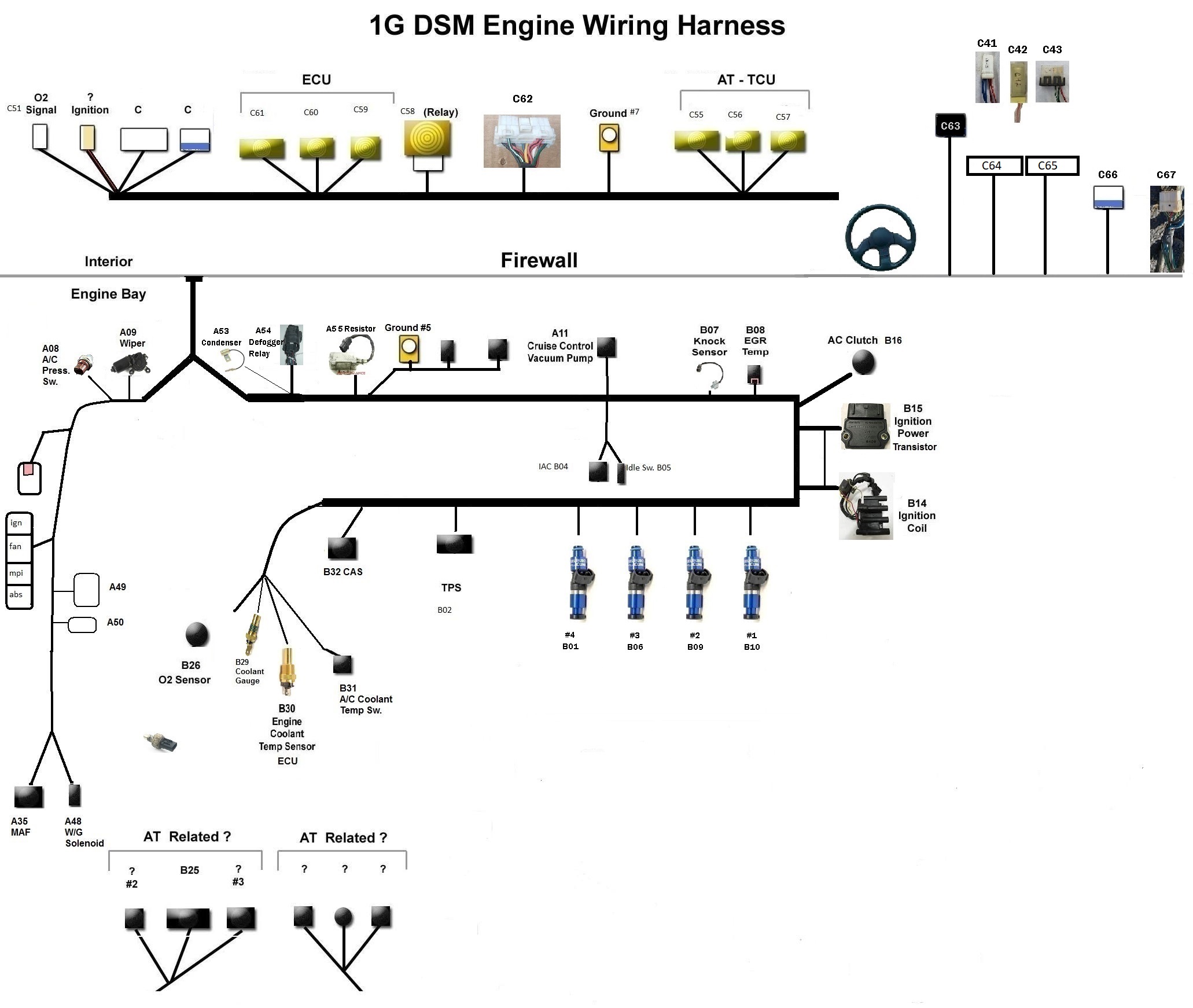
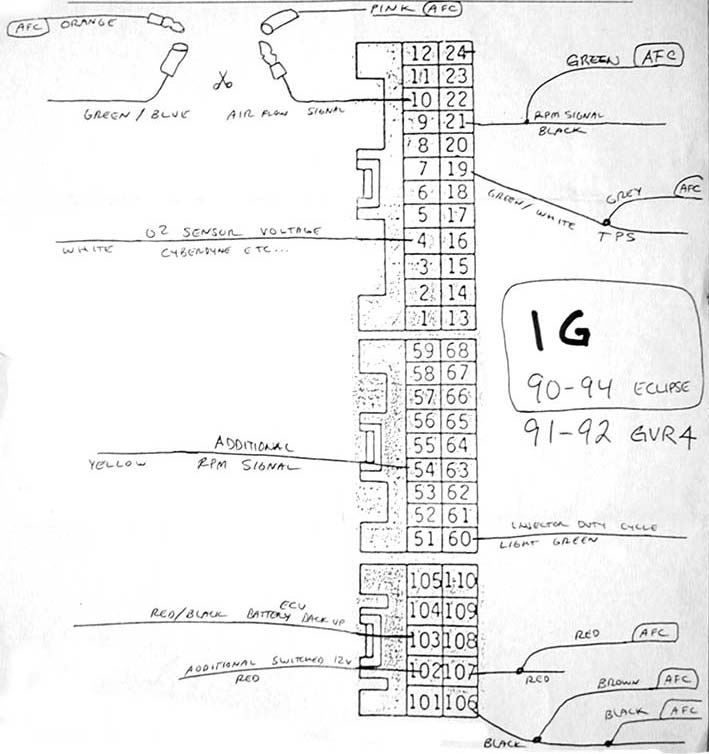
The ds0 rate and its equivalents e0 in the e carrier system and t0 in the t carrier system form the basis for the digital multiplex transmission hierarchy in telecommunications systems used in north america. This page contains basic wiring information for the ecu connector in a 1g and 2g dsm.
Dsm Injectors On 92 Integra Wiring Complexity Honda
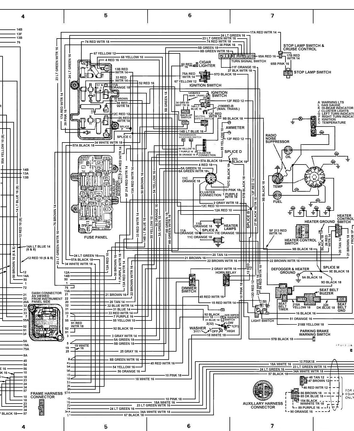
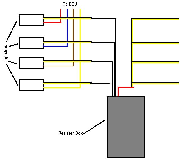
Dsm wiring diagram. Most importantly it shows the mpi relay which is the most challenging part to understand. The diagrams do not illustrate the wiring connectors in the car. Many people will assume the diagrams show you looking into the wiring connectors in the car. Please note that the diagrams are all shown as you are looking into the ecu connectors on the ecu itself with the male pins pointing out at you. Eat sleep dsm custom wiring makes custom dsm wiring harnesses using your wiring harness as a base. According to robert arrowood tyler hodgson and micheal astor 1g talons and lasers have the fog light wiring installed even if they did not come with the actual lights.
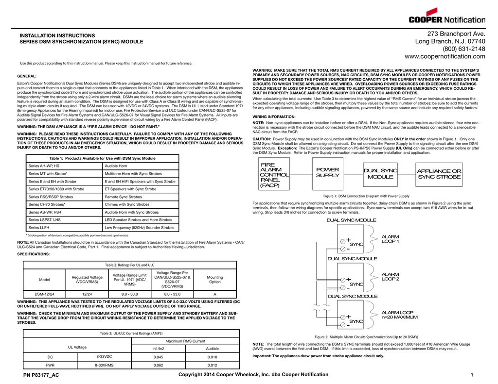
Digital signal 0 ds0 is a basic digital signaling rate of 64 kilobits per second corresponding to the capacity of one analog voice frequency equivalent communication channel. One is a wiring diagram for a 1990 4g63 dsm. Every harness is different and built exactly for your needs and your setup. If you are planning a wire tuck a custom wiring harness is a must. Dsm sync modules shall mount to a 4 1116 x 2 18 deep backbox. Strip leads 38 inches for connection to screw terminals.
And shall incorporate screw terminals for inout fieldwiring of 18 to 12 awg wire size. Dsm connection diagram with power booster description. Architects and engineers specifications s3000 dsm 0611. Variety of raymarine seatalk wiring diagram. With that said hopefully some people will find these diagrams beneficial. Is the wiring harness for stock fog lights installed on a dsm that didnt come with them installed.
The dsm 1224 sync modules control either one 1 class a or two 2 class b nac. Compatible with standard fire alarm systems the wheelock dsm sync modules provide independent operation of synchronized temporal pattern code 3 horn and synchronized strobe flash as well as the ability to silence the horn while maintaining the strobe flash audible silence using only a single pair of wires. Each one shows how the wiring harness needs to be setup for an engine swap. The other is the wiring diagram for a 1991 94 4g63 dsm. Wiring diagram for llfh sync strobes red and black shunt wires are supplied with dsm wiring and mounting. We can do several different things and build your harness exactly how you want it.
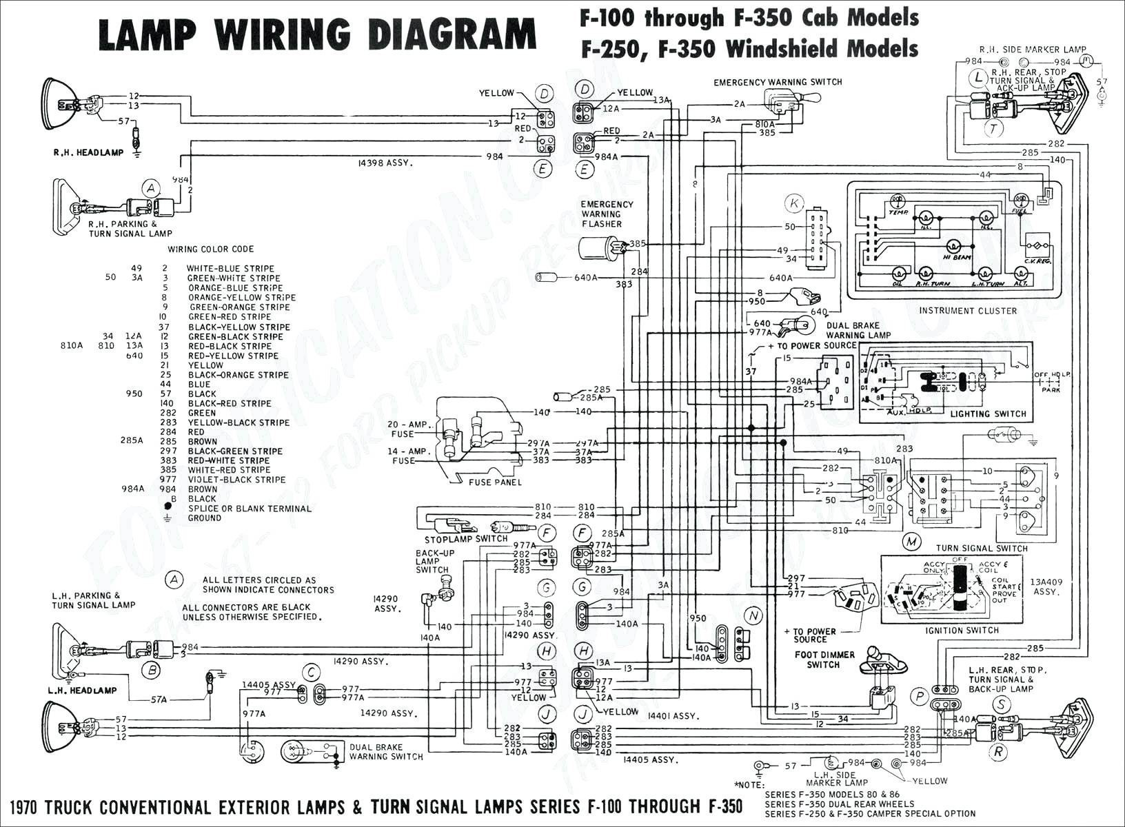
Dual sync modules have in out appliance circuit wiring terminals that accepts two 12 to 18 awg wires at each screw terminal. It shows the parts of the circuit as simplified forms as well as the power and signal links in between the tools. A wiring diagram is a streamlined traditional pictorial representation of an electric circuit.
Gallery of Dsm Wiring Diagram