The dt 300 series dual technology ceiling sensors combine the benefits of passive infrared pir and ultrasonic technologies to detect occupancy. When using more sensors than this multiple power packs are required.
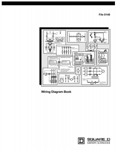
Wiring Diagram Book Schneider Electric
Dt 305 wiring diagram. Sensors have a flat unobtrusive appearance and provide 360 degrees of coverage. Voltage current coverage features sensors are white and use watt stopper power packs. Wattstopper dt 305 wiring diagram. When using more sensors than this multiple power packs are required. Refer to the wiring diagram on the next page for the following procedures. Wiring directions each wattstopper bz series power pack can supply power for 5 dt 305 sensors.
Connect the low voltage. Wiring directions each wattstopper bz series power pack can supply power for 7 dt 305 sensors. Refer to the wiring diagram on the next page for the following procedures. 1967 shelby gt500 barn find and appraisal that buyer uses to pay widow price revealed duration. Red wire 24vdc from power pack to the 24v terminal on the sensor. Connect the low voltage.
Wiring directions each wattstopper bz series power pack can supply power for 6 dt 300 sensors. 06012019 06012019 7 comments on wattstopper dt 305 wiring diagram. Connect the low voltage. Refer to the wiring diagram on the next page for the following procedures. Refer to the wiring diagram on the next page for the following procedures. Connect the low voltage.
Connect the low voltage. Wattstopper products services 42037 views. 43 ma 35 ma up to 1000 ft2 929 m2 up to 1000 ft2 929 m2 isolated relay light level wiring diagram. Wiring directions each wattstopper bz series power pack can supply power for 7 dt 305 sensors. Current consumption can be slightly higher when only one sensor per power pack is used. Each watt stopper bz series power pack can supply power for 4 dt 305 sensors.
Low voltage momentary switch to the above applications see wiring diagram accessories wattstopper ut installation instructions manual. Wiring a bz 150 universal voltage power pack duration. Learn how to correctly wire a dt 305 dual technology ceiling sensor. Refer to the wiring diagram on the next page for the following procedures. Plug terminal wiring for quick and easy installation. The low profile dt dual.
View and download wattstopper dt installation instructions manual online. Red wire 24vdc from power pack to the 24v terminal on the sensor. Dt 300 dt 305 24 vdcvac 24 vdcvac catalog no. When using more sensors than this multiple power packs are required. When using more sensors than this multiple power packs are required. Dt 305 installation instructions.
Wiring directions each watt stopper b series power pack can supply power for up to 3 dt 305 sensors. When using more sensors than this multiple power packs are required. Jerry heasley recommended for you. Red wire 24vdc from power pack to the 24v terminal on the sensor. Red wire 24vdc from power pack to the 24v terminal on the sensor.
Gallery of Dt 305 Wiring Diagram