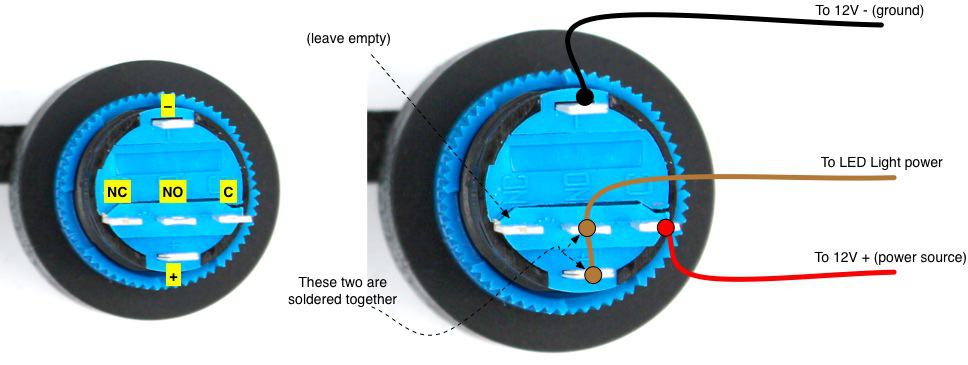
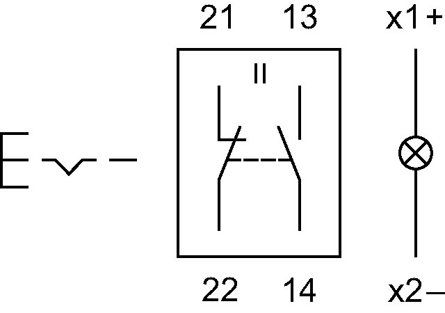
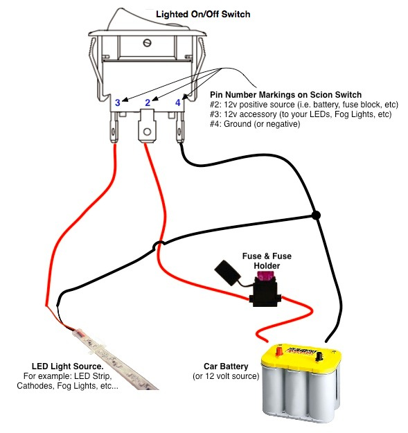
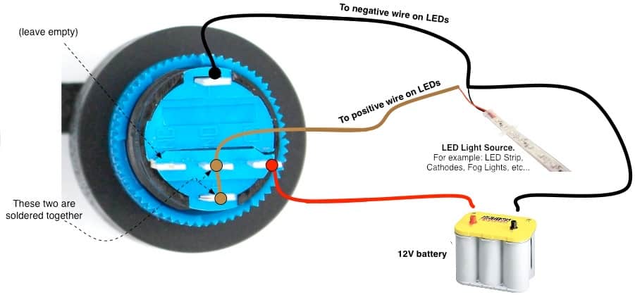
I realize the x1 x2 connections are for the illumination and needs to be jumped. T w 6.
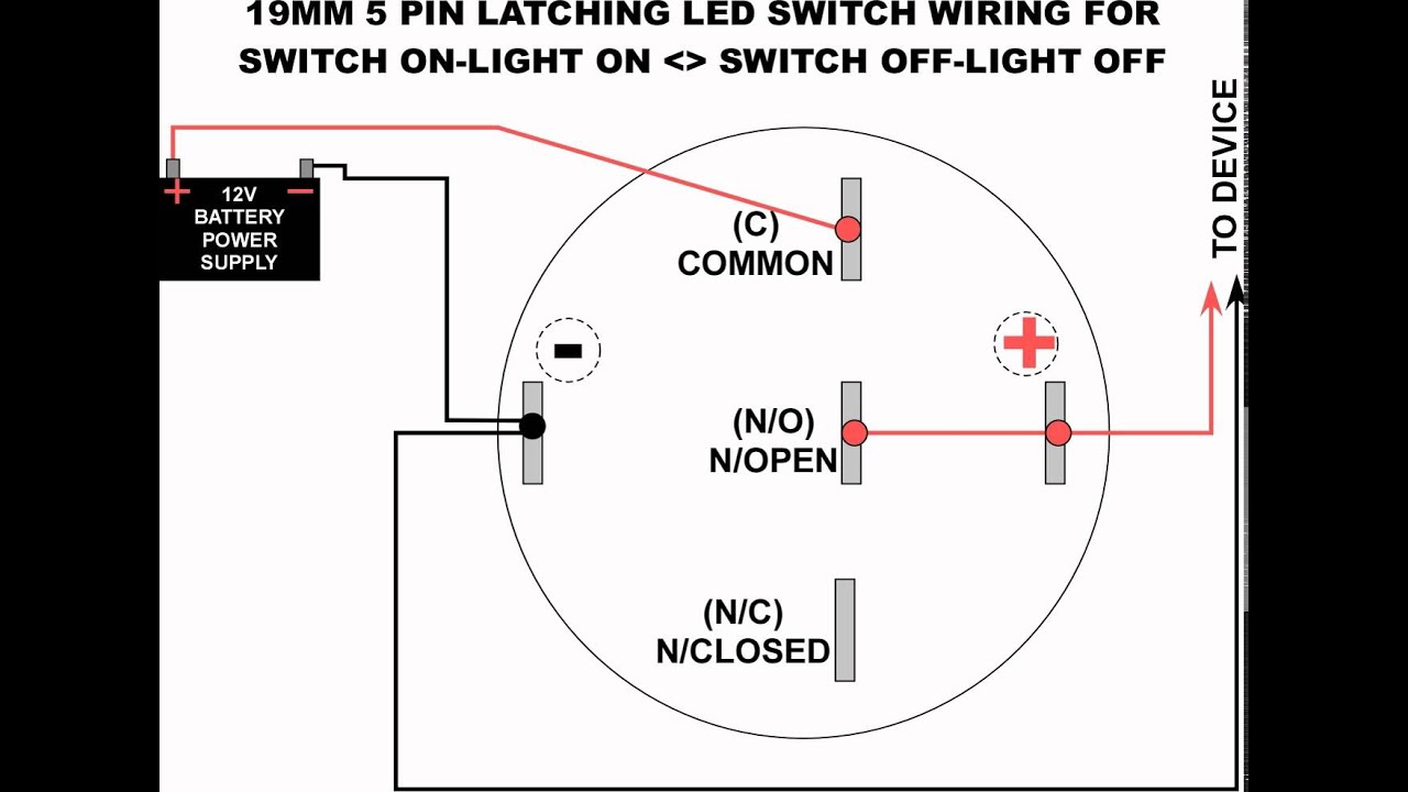
19mm Led Latching Switch Wiring Diagram
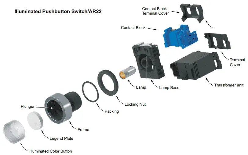
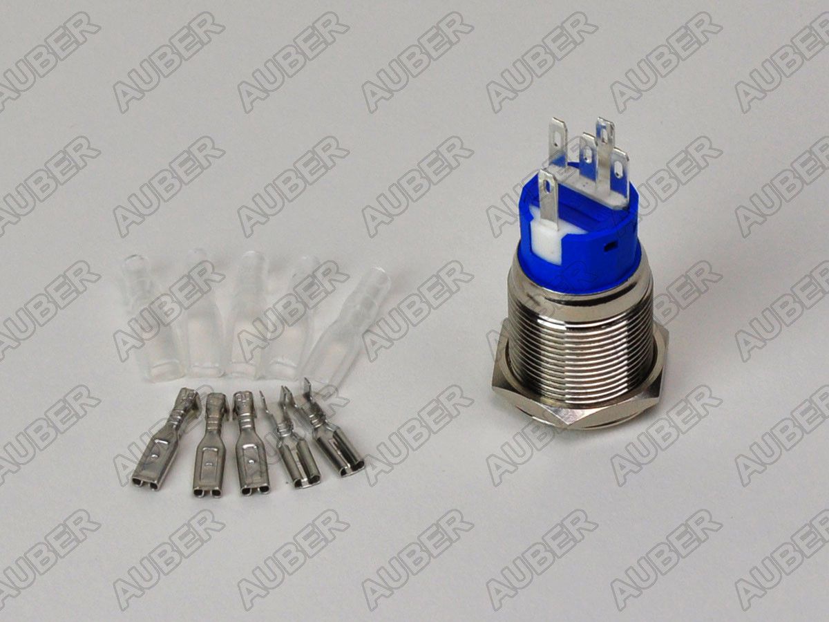
Illuminated push button switch wiring diagram. Push button switch working principle. Their are 6 terminal connections 2 for illumination 2 for no and 2 for nc sides. Typical wiring diagrams for push button control stations 7 start stop control wiring diagrams single station with motor stopped pilot light l1 start l2 i 1 stop 2 oi 3 n wol. Pilot light l2 4 2 3 pilot light start stop bulletin 1495 normally closed auxiliary contacts are required. Through hole mounting design. This is a wiring diagram to illustrate how to wire up your spst rocker switch for your vapoven elements battery deluxe diy induction heater kit though the principles should apply to most similar boards.
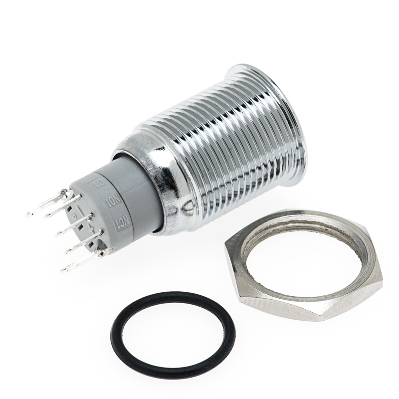
I have wiring hooked up to terminals 13 and 14 which are the normally open contacts. They contain a set of contact plates that make or break when activated by someone. 120896 5900 x 24vdc fail secure strike. C i m nc. They are 1no1nc illuminated switches. There is also an illuminated push button wiring diagram here and a complete kit wiring diagram here.
Here is an easy to follow instructional video with all install diagrams for our range of stedi oem and carling type switches. Push buttons are simple single pole switches. Push button carling type rocker switch wiring instructions our oem type switches are the perfect finishing touch for stealth oem like install. All push buttons are made the same way what gives them their special characteristics or function is the legend plate and sometimes the operator or button head. This can be accomplished with any of securitrons push buttons and the model tm 8l timer.
Gallery of Illuminated Push Button Switch Wiring Diagram