If the difference is increased by some limit an alarm will be generated. In this diagram two duplex receptacle outlets are installed in the same box and wired separately to the source using pigtails spliced to connect the terminals of each one.
Difference Between 2 Wire Rtd 3 Wire Rtd And 4 Wire Rtd S
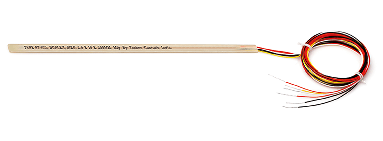
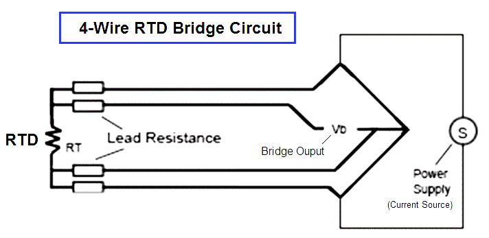
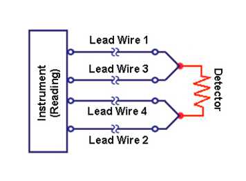
Duplex rtd wiring diagram. Duplex 3 wire rtd connection as per single rtd but two individual element windings. Now coming to the advantagesapplications. 4 wire connection is the most accurate measurement. Duplex pt100 sensors use two junctions in one sensor. Simplex rtd having only one sensor in the rtd. 4 wire rtd signal connection connect each of the red leads on the positive side of the resistive element to the excitation positive and channel positive on the daq device.
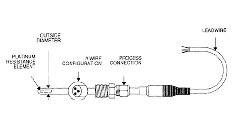
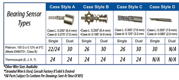
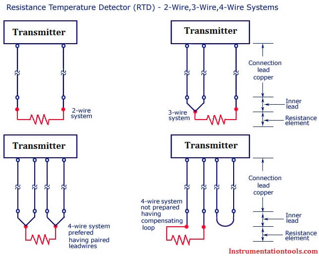
The following connection diagrams illustrate how to connect various rtd types to your daq device. 2 wire rtd connections the 2 wire rtd configuration is the simplest among rtd circuit designs. The graph below shows the temperature error from 2 leads of various sizes and lengths for a 100 ohm platinum rtd at 100c. First of all lead wire resistance has nothing to do with simplexduplex rtds. Rtd 2 page rtd 3 page rtd 4 page rtd 5 page rtd 6 1 1 duplex platinum rtd elements 1 2 available sheath diameters 316ss code initial element accuracy at 0 ºc base resistance at 0 ºc temperature coefficient code low range wire wound 200 to 204 ºc 316 od 14 od 38 od. Wiring diagram for a 20 amp 120 volt duplex receptacle a 20 amp 120v duplex receptacle outlet like this should be installed in a circuit using 12 awg cable and a 20 amp circuit breaker.
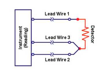
2 lead constructions result in leadwire resistance getting added to the element resistance. The instrument measures the lead resistance of all four lead wires removing these values for its reading. In duplex type rtd there will be 2 temperature sensing elements of 3 wires each. Consequently the temperature reading is artificially high. Duplex pt100s are used in applications where downtime must be kept to a minimum one rtd element will be used until it reaches the end of its lifespan then the wire can be quickly swapped round to the other rtd element and a replacement sensor can be ordered. Duplex rtd have two sensors in single rtd which is used as redundant sensor in critical applications.
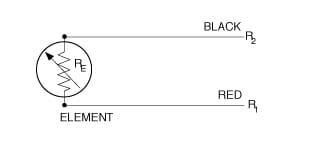
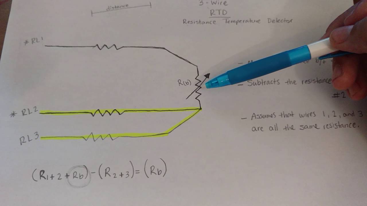
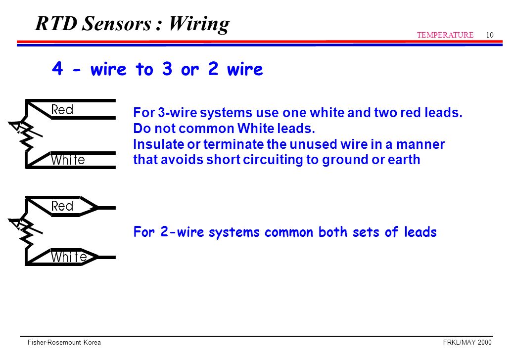
Rtd wiring configurations there are three types of wire configurations 2 wire 3 wire and 4 wire that are commonly used in rtd sensing circuits. Connect the black or white lead on the negative side for the resistive. In simplex type rtds there will be only one element with 3 wires. Some times duplex rtds are used to find healthiness of sensor by measuring the difference between two sensors. A 2 wire configuration with a compensating loop is also an option. These receptacles are usually found in kitchen wall outlets where two branch circuits are needed to serve small appliances and a refrigerator separately.
With each outlet connected by its own pigtail wire if one fails because of physical damage the other wont be affected and should still work. In any rtd with 3 wires 3rd wire acts as the compensation wire.
Gallery of Duplex Rtd Wiring Diagram