Duraspark wiring diagram wiring diagram is a simplified good enough pictorial representation of an electrical circuitit shows the components of the circuit as simplified shapes and the power and signal connections amid the devices. My girlfriends dad just bought me a duraspark ignition i think its a 1.
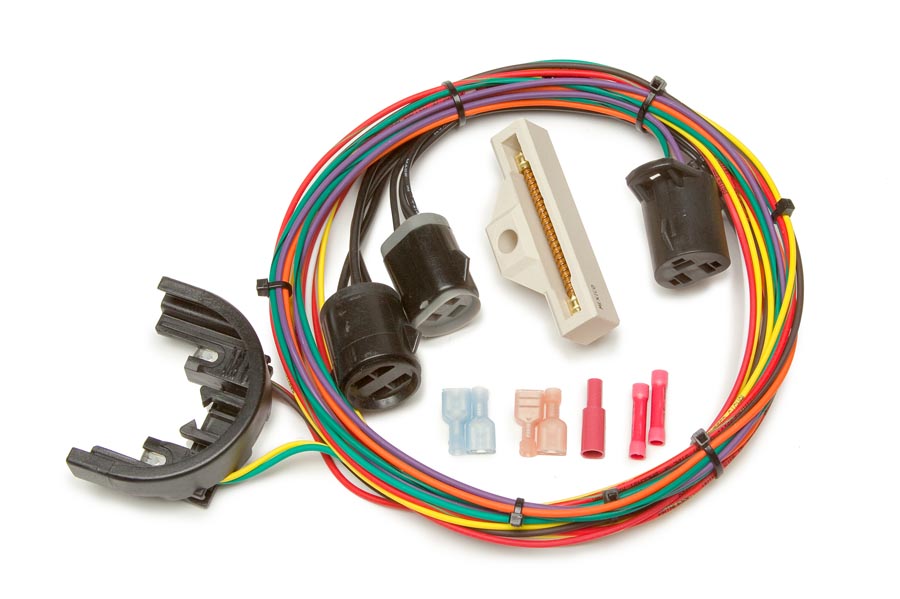
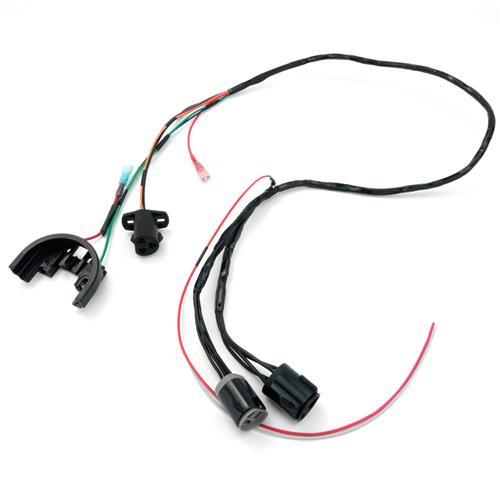
Duraspark Ii Ignition Harness Painless Performance
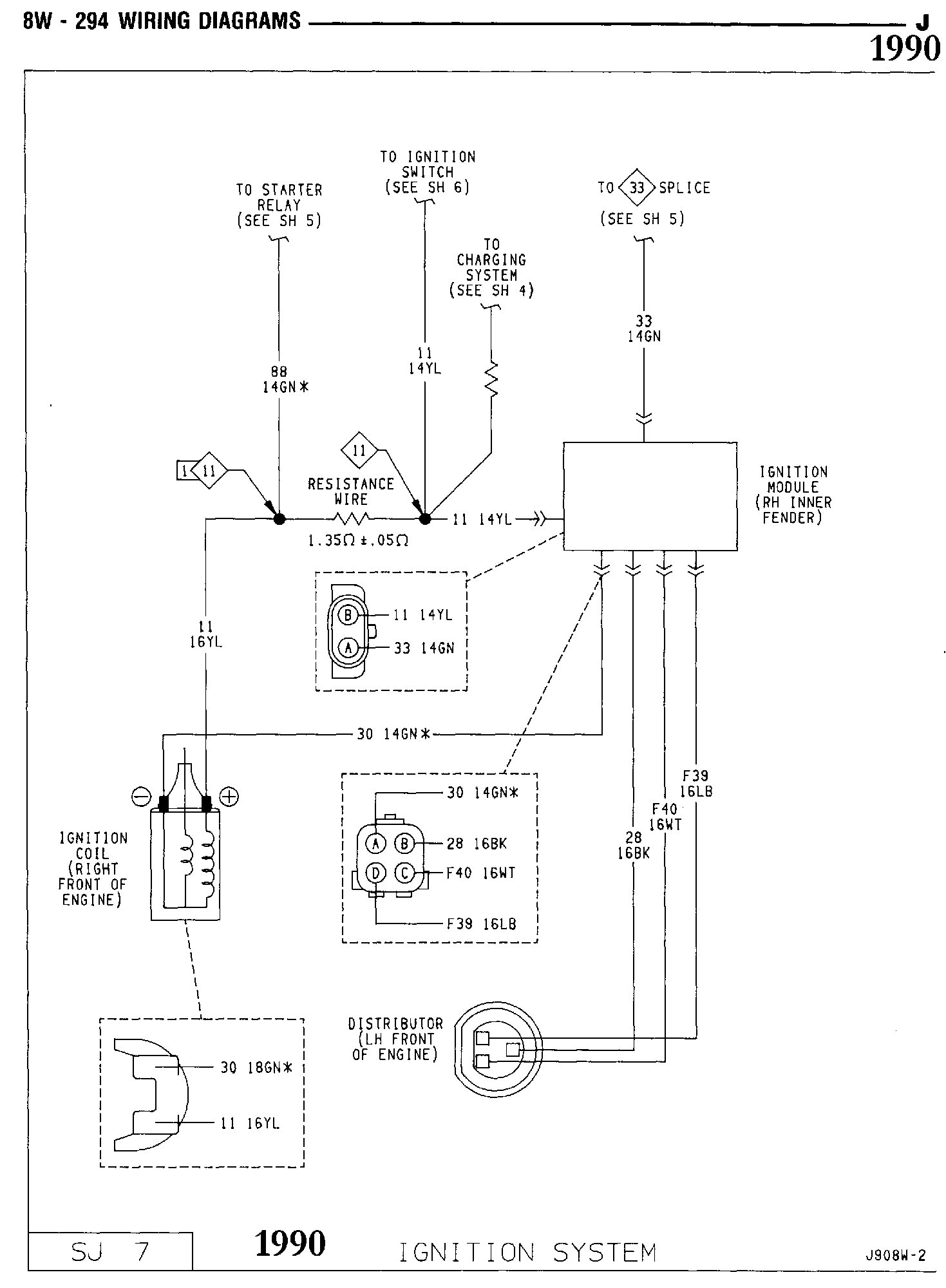
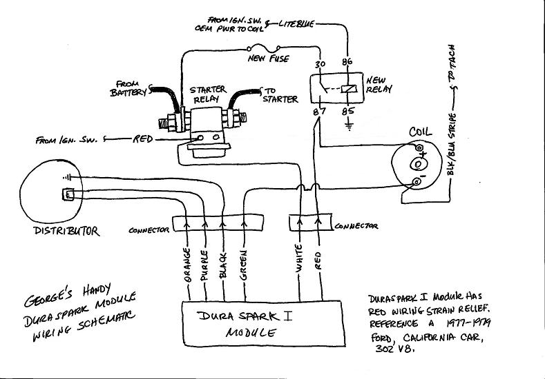
Duraspark 1 wiring diagram. A wiring diagram usually gives opinion approximately the relative aim and contract of devices and terminals on the devices to back in building or servicing. Duraspark ii wiring diagram. Is there any difference between a 1 or 2. 1985 ford duraspark wiring diagram wiring diagram duraspark 2 wiring diagram. According to the duraspark wiring diagram the white wire connects with the s on the starter solenoid but it is on i. Detailed instructions on how to put this in will be greatly appreciated.
These directions will probably be easy to grasp and apply. Ford duraspark wiring diagram 1975 ford duraspark wiring diagram 1977 ford duraspark wiring diagram 1979 ford duraspark wiring diagram every electrical arrangement is made up of various different pieces. Wiring diagram comes with a number of easy to adhere to wiring diagram directions. It is intended to help all the average consumer in creating a correct method. A wire connects s with the ignition switch. Each component ought to be set and connected with different parts in specific manner.
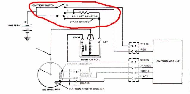
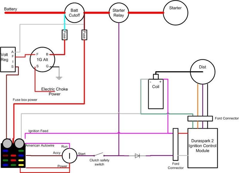
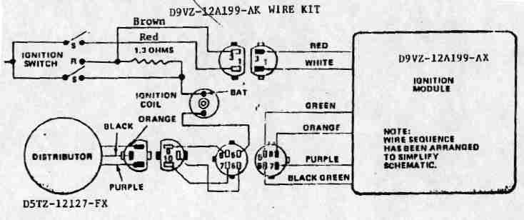
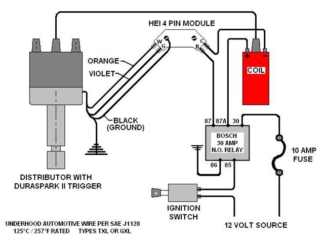
That means a ballast resistor or resistor wire needs to be used. With a one can i still run a diffenent coil like accell from my local autoparts store. Just yesterday i fired up my truck for the first time after dirtdonk helped me through my duraspark wiring. White wire s terminal on the solenoid red wire keyed 12v green w yellow dashes negative terminal on coil. The system consists of the distributor coil external amplifier box wiring and connectors. Otherwise the structure wont function as it should be.
If the original duraspark ii coil is to be used it needs to be supplied with about 9 vdc not full battery current. Heres what i have colors based on blue grommet module and factory wiring. The red wire should connect with the coil terminal but is connected with the battery terminal directly.
Gallery of Duraspark 1 Wiring Diagram